MPC5604B/C Microcontroller Reference Manual, Rev. 8
Freescale Semiconductor 271
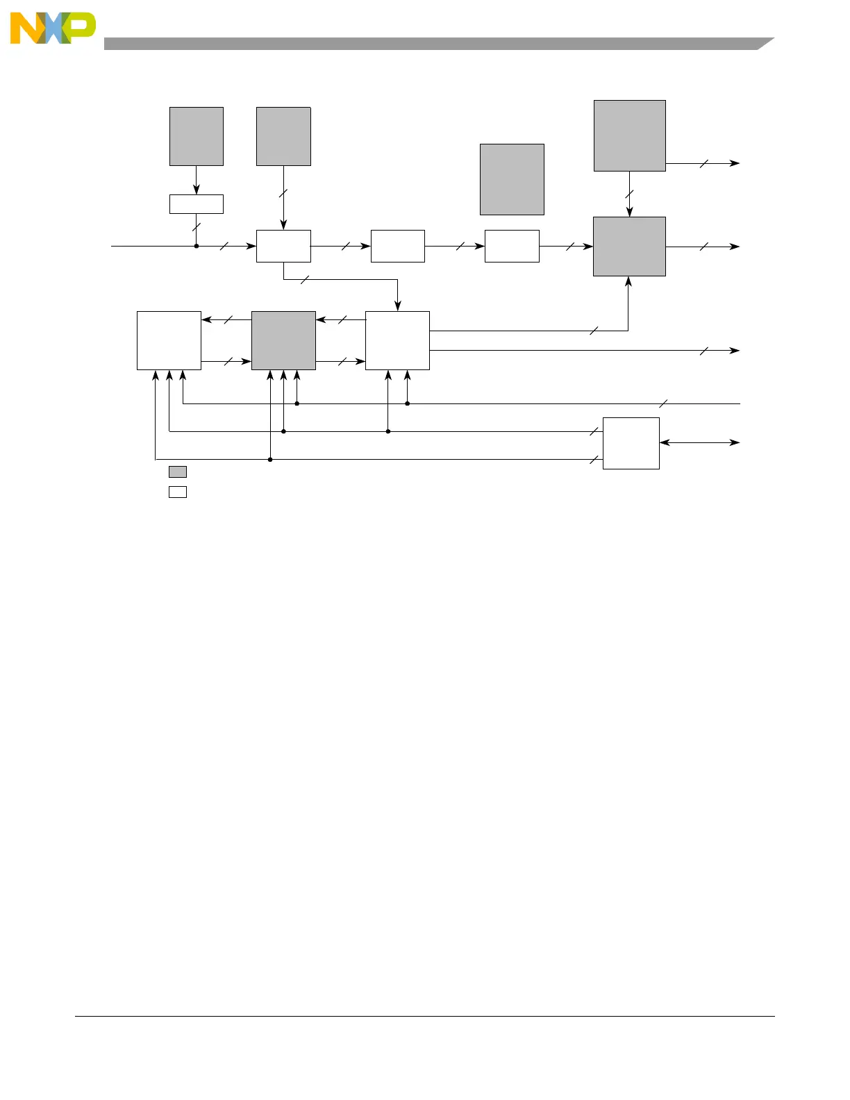
Figure 16-1. INTC block diagram
16.4 Modes of operation
16.4.1 Normal mode
In normal mode, the INTC has two handshaking modes with the processor: software vector mode and
hardware vector mode.
16.4.1.1 Software vector mode
In software vector mode, software, that is the interrupt exception handler, must read a register in the INTC
to obtain the vector associated with the interrupt request to the processor. The INTC will use software
vector mode for a given processor when its associated HVEN bit in INTC_MCR is negated. The hardware
vector enable signal to processor 0 or processor 1 is driven as negated when its associated HVEN bit is
negated. The vector is read from INC_IACKR. Reading the INTC_IACKR negates the interrupt request
to the associated processor. Even if a higher priority interrupt request arrived while waiting for this
interrupt acknowledge, the interrupt request to the processor will negate for at least one clock. The reading
also pushes the PRI value in INTC_CPR onto the associated LIFO and updates PRI in the associated
INTC_CPR with the new priority.
Furthermore, the interrupt vector to the processor is driven as all 0s. The interrupt acknowledge signal
from the associated processor is ignored.
Hardware
Vector Enable
Software
Set/Clear
Interrupt
Registers
Flag Bits
Priority
Select
Registers
Peripheral
Interrupt
Requests
Module
Configuration
Register
Highest Priority
4
Priority
Comparator
Slave
Interface
for Reads
& Writes
1
Push/Update/Acknowledge
1
1
1
Update Interrupt Vector
1
Interrupt
Request to
Processor
Memory Mapped Registers
Non-Memory Mapped Logic
End of
Interrupt
Register
Request
Selector
Priority
Arbitrator
Highest
Priority
Interrupt
Requests
n
1
n
1
Vector
Encoder
Interrupt
Vector
9
Processor 0
Interrupt
Acknowledge
Register
Interrupt
Vector
9
n
1
8
n
1
x
4-bits
New
Priority
4
Current
Priority
4
Processor 0
Current
Priority
Register
Processor 0
Priority
LIFO
Pop
1
Lowest
Vector
Interrupt
Request
1
Vector Table
Entry Size
Pushed
Priority
4
Popped
Priority
4
Interrupt Acknowledge
Peripheral
Bus