MPC5604B/C Microcontroller Reference Manual, Rev. 8
246 Freescale Semiconductor
and associated interrupts are optionally enabled. In low power mode, the bus interface is disabled and the
input isolation is enabled. The RTC/API is enabled if enabled prior to entry into low power mode.
13.4.2 Debug mode
On entering into the debug mode the RTC counter freezes on the last valid count if the RTCC[FRZEN] is
set. On exit from debug mode counter continues from the frozen value.
13.5 Register descriptions
Table 13-1 lists the RTC/API registers.
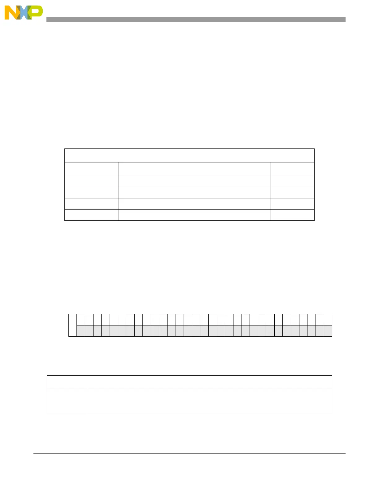
13.5.1 RTC Supervisor Control Register (RTCSUPV)
The RTCSUPV register contains the SUPV bit which determines whether other registers are accessible in
supervisor mode or user mode.
NOTE
RTCSUPV register is accessible only in supervisor mode.
Table 13-1. RTC/API register map
Base address: 0xC3FE_C000
Address offset Register Location
0x0 RTC Supervisor Control Register (RTCSUPV) on page 246
0x4 RTC Control Register (RTCC) on page 247
0x8 RTC Status Register (RTCS) on page 249
0xC RTC Counter Register (RTCCNT) on page 250
Offset: 0x0 Access: Read/write
012345678910111213141516171819202122232425262728293031
R
SUPV
W
Reset10000000000000000000000000000000
Figure 13-3. RTC Supervisor Control Register (RTCSUPV)
Table 13-2. RTCSUPV field descriptions
Field Description
SUPV RTC Supervisor Bit
0 All registers are accessible in both user as well as supervisor mode.
1 All other registers are accessible in supervisor mode only.