MPC5604B/C Microcontroller Reference Manual, Rev. 8
586 Freescale Semiconductor
24.5.5 Functional description
24.5.5.1 General
This section gives detailed information on the internal operation of the module. Each timer can be used to
generate trigger pulses as well as to generate interrupts, each interrupt will be available on a separate
interrupt line.
24.5.5.1.1 Timers
The timers generate triggers at periodic intervals, when enabled. They load their start values, as specified
in their LDVAL registers, then count down until they reach 0. Then they load their respective start value
again. Each time a timer reaches 0, it will generate a trigger pulse and set the interrupt flag.
All interrupts can be enabled or masked (by setting the TIE bits in the TCTRL registers). A new interrupt
can be generated only after the previous one is cleared.
If desired, the current counter value of the timer can be read via the CVAL registers.
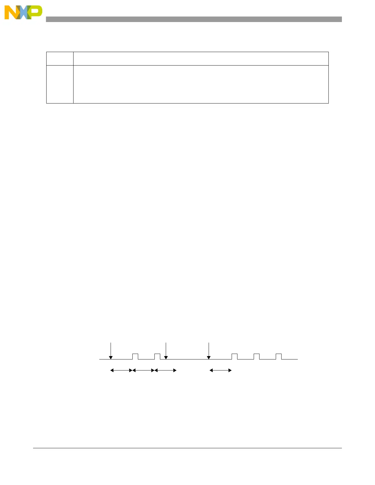
The counter period can be restarted, by first disabling, then enabling the timer with the TEN bit (see
Figure 24-62).
The counter period of a running timer can be modified, by first disabling the timer, setting a new load value
and then enabling the timer again (see Figure 24-63).
It is also possible to change the counter period without restarting the timer by writing the LDVAL register
with the new load value. This value will then be loaded after the next trigger event (see Figure 24-64).
Figure 24-62. Stopping and starting a timer
Table 24-29. TFLG field descriptions
Field Description
TIF Time Interrupt Flag
TIF is set to 1 at the end of the timer period. This flag can be cleared only by writing it with a 1. Writing a
0 has no effect. If enabled (TIE = 1), TIF causes an interrupt request.
0 Time-out has not yet occurred
1 Time-out has occurred
p1p1
Timer Enabled Disable
Timer
p1
Start Value = p1
Trigger
Event
p1
Re-Enable
Timer


 To Next Page