MPC5604B/C Microcontroller Reference Manual, Rev. 8
518 Freescale Semiconductor
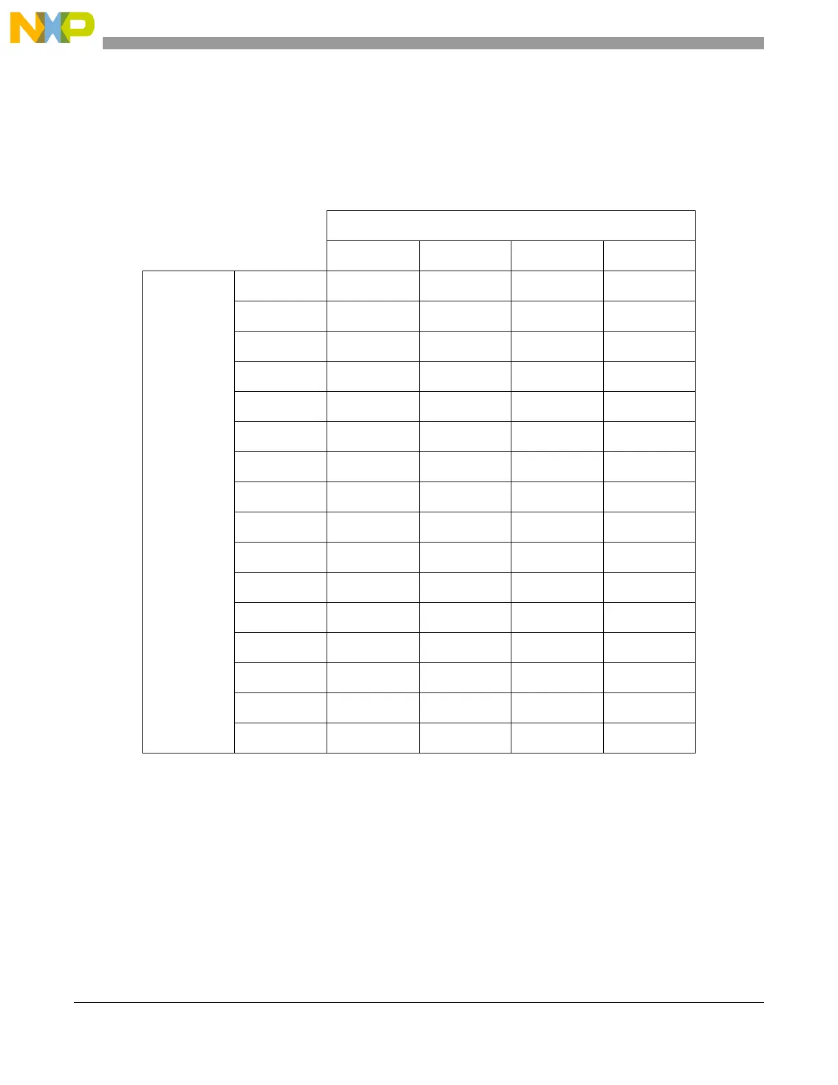
23.7.3 Delay settings
Table 23-34 shows the values for the delay after transfer (t
DT
) that can be generated based on the prescaler
values and the scaler values set in the DSPIx_CTARs. The values calculated assume a 64 MHz system
frequency.
23.7.4 Calculation of FIFO pointer addresses
The user has complete visibility of the TX and RX FIFO contents through the FIFO registers, and valid
entries can be identified through a memory mapped pointer and a memory mapped counter for each FIFO.
The pointer to the first-in entry in each FIFO is memory mapped. For the TX FIFO the first-in pointer is
the transmit next pointer (TXNXTPTR). For the RX FIFO the first-in pointer is the pop next pointer
(POPNXTPTR).
Table 23-34. Delay values
Delay prescaler values (DSPI_CTAR[PDT])
1357
Delay scaler values (DSPI_CTAR[DT])
2
31.25 ns 93.75 ns 156.25 ns 218.75 ns
4
62.5 ns 187.5 ns 312.5 ns 437.5 ns
8
125 ns 375 ns 625 ns 875 ns
16
250 ns 750 ns 1.25 µs 1.75 µs
32
0.5 µs 1.5 µs 2.5 µs 3.5 µs
64
1 µs 3 µs 5 µs 7 µs
128
2 µs 6 µs 10 µs 14 µs
256
4 µs 12 µs 20 µs 28 µs
512
8 µs 24 µs 40 µs 56 µs
1024
16 µs 48 µs 80 µs 112 µs
2048
32 µs 96 µs 160 µs 224 µs
4096
64 µs 192 µs 320 µs 448 µs
8192
128 µs 384 µs 640 µs 896 µs
16384
256 µs 768 µs 1.28 ms 1.79 ms
32768
512 µs 1.54 ms 2.56 ms 3.58 ms
65536
1.02 ms 3.07 ms 5.12 ms 7.17 ms