MPC5604B/C Microcontroller Reference Manual, Rev. 8
240 Freescale Semiconductor
An NMI supports a status flag and an overrun flag which are located in the NSR register (see Figure 12-2).
The NIF0 and NOVF0 fields in this register are cleared by writing a ‘1’ to them; this prevents inadvertent
overwriting of other flags in the register. The status flag is set whenever an NMI event is detected. The
overrun flag is set whenever an NMI event is detected and the status flag is set (that is, has not yet been
cleared).
NOTE
The overrun flag is cleared by writing a ‘1’ to the appropriate overrun bit in
the NSR register. If the status bit is cleared and the overrun bit is still set, the
pending interrupt will not be cleared.
12.5.3 External wakeups/interrupts
The Wakeup Unit supports up to 18 external wakeup/interrupts which can be allocated to any pad
necessary at the SoC level. This allocation is fixed per SoC.
The Wakeup Unit supports up to three interrupt vectors to the interrupt controller of the SoC. Each
interrupt vector can support up to the number of external interrupt sources from the device pads with the
total across all vectors being equal to the number of external interrupt sources. Each external interrupt
source is assigned to exactly one interrupt vector. The interrupt vector assignment is sequential so that one
interrupt vector is for external interrupt sources 0 through N-1, the next is for N through N+M-1, and so
forth.
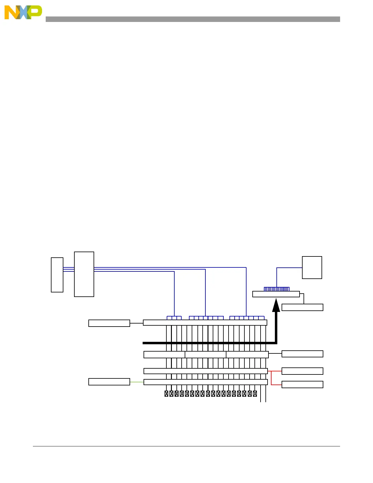
See Figure 12-12 for an overview of the external interrupt implementation for the example of three
interrupt vectors with up to eight external interrupt sources each.
Figure 12-12. External interrupt pad diagram
Interrupt
Vectors
Pads
WIREER[19:0]
Interrupt Edge Enable
WIFEER[19:0]
Falling
Rising
Edge Detection
Analog Glitch Filter
WIFER[19:0]
Glitch Filter enable
Interrupt enable
OR OR OR
IRQ_19_16 IRQ_15_08 IRQ_07_00
Flag[19:16] Flag[15:8]
WISR[19:0]
Flag[7:0]
WRER[19:0]
Wakeup enable
Mode /
Pwr Ctl
IRER[19:0]
RTC API
Interrupt
Controller