MPC5604B/C Microcontroller Reference Manual, Rev. 8
352 Freescale Semiconductor
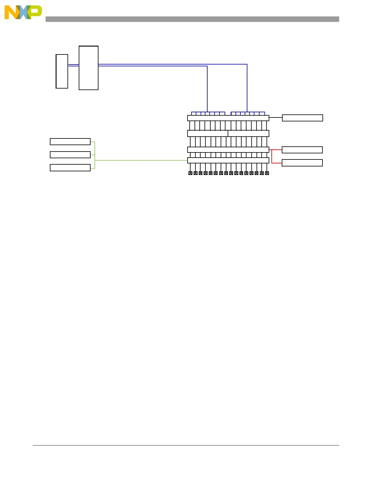
Figure 19-16. External interrupt pad diagram
1
This value is valid in the 144-pin LQFP and the 208-pin packages, while there are 12 interrupts in the 100-pin LQFP packages
Each interrupt can be enabled or disabled independently. This can be performed using the IRER. A pad
defined as an external interrupt can be configured to recognize interrupts with an active rising edge, an
active falling edge or both edges being active. A setting of having both edge events disabled is reserved
and should not be configured.
The active EIRQ edge is controlled through the configuration of the registers IREER and IFEER.
Each external interrupt supports an individual flag which is held in the Interrupt Status Flag Register (ISR).
The bits in the ISR[EIF] field are cleared by writing a ‘1’ to them; this prevents inadvertent overwriting of
other flags in the register.
19.7 Pin muxing
For pin muxing, please see the signal description chapter of this reference manual.
Interrupt
Controller
Interrupt
Vectors
EIF[15:8]
1
EIF[7:0]
IRE[15:0]
1
Pads
IREE[15:0]
1
Interrupt Edge Enable
IFEE[15:0]
1
Falling
Rising
Edge Detection
Glitch Filter
IFE[15:0]
1
MAXCOUNT[x]
IRQ Glitch Filter enable
Glitch filter Counter_n
IFCP[3:0]
Glitch filter Prescaler
Interrupt enable
OR OR
IRQ_15_08
1
IRQ_07_00