MPC5604B/C Microcontroller Reference Manual, Rev. 8
Freescale Semiconductor 511
When the CONT bit = 1 and the CS signals for the next transfer are different from the present transfer, the
CS signals behave as if the CONT bit was not set.
NOTE
You must fill the TXFIFO with the number of entries that will be
concatenated together under one PCS assertion for both master and slave
before the TXFIFO becomes empty. For example; while transmitting in
master mode, ensure that the last entry in the TXFIFO, after which TXFIFO
becomes empty, has CONT = 0 in the command frame.
When operating in slave mode, ensure that when the last-entry in the
TXFIFO is completely transmitted (i.e. the corresponding TCF flag is
asserted and TXFIFO is empty) the slave is deselected for any further serial
communication; otherwise, an underflow error occurs.
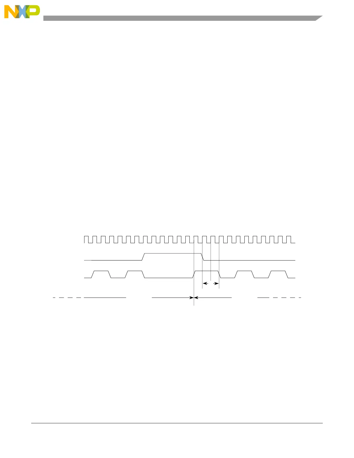
23.6.5.6 Clock polarity switching between DSPI transfers
If it is desired to switch polarity between non-continuous DSPI frames, the edge generated by the change
in the idle state of the clock occurs one system clock before the assertion of the chip select for the next
frame.
See Section 23.5.4, DSPI Clock and Transfer Attributes Registers 0–5 (DSPIx_CTARn).
In Figure 23-22, time ‘A’ shows the one clock interval. Time ‘B’ is user programmable from a minimum
of two system clocks.
Figure 23-22. Polarity switching between frames
23.6.6 Continuous serial communications clock
The DSPI provides the option of generating a continuous SCK signal for slave peripherals that require a
continuous clock.
Continuous SCK is enabled by setting the CONT_SCKE bit in the DSPIx_MCR. Continuous SCK is valid
in all configurations.
Continuous SCK is only supported for CPHA = 1. Setting CPHA = 0 is ignored if the CONT_SCKE bit is
set. Continuous SCK is supported for modified transfer format.
CS
System clock
SCK
Frame 1
Frame 0
CPOL = 0 CPOL = 1
AB