MPC5604B/C Microcontroller Reference Manual, Rev. 8
512 Freescale Semiconductor
Clock and transfer attributes for the continuous SCK mode are set according to the following rules:
• The TX FIFO must be cleared before initiating any SPI configuration transfer.
• When the DSPI is in SPI configuration, CTAR0 is used initially. At the start of each SPI frame
transfer, the CTAR specified by the CTAS for the frame should be CTAR0.
• In all configurations, the currently selected CTAR remains in use until the start of a frame with a
different CTAR specified, or the continuous SCK mode is terminated.
The device is designed to use the same baud rate for all transfers made while using the continuous SCK.
Switching clock polarity between frames while using continuous SCK can cause errors in the transfer.
Continuous SCK operation is not guaranteed if the DSPI is put into module disable mode.
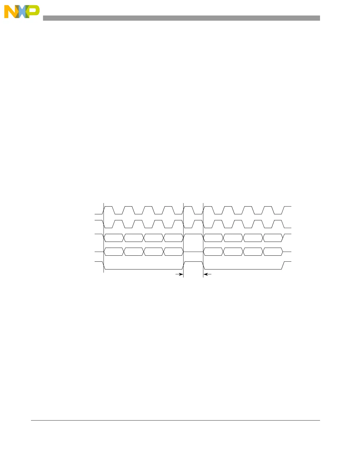
Enabling continuous SCK disables the CS to SCK delay and the After SCK delay. The delay after transfer
is fixed at one SCK cycle. Figure 23-23 shows timing diagram for continuous SCK format with continuous
selection disabled.
NOTE
When in Continuous SCK mode, always use CTAR0 for the SPI transfer,
and clear the TXFIFO using the MCR[CLR_TXF] field before initiating
transfer.
Figure 23-23. Continuous SCK timing diagram (CONT= 0)
If the CONT bit in the TX FIFO entry is set, CS remains asserted between the transfers when the CS signal
for the next transfer is the same as for the current transfer. Figure 23-24 shows timing diagram for
continuous SCK format with continuous selection enabled.
SCK
(CPOL = 0)
CS
SCK
(CPOL = 1)
Master SOUT
t
DT
t
DT
= 1 SCK
Master SIN
 Loading...