MPC5604B/C Microcontroller Reference Manual, Rev. 8
64 Freescale Semiconductor
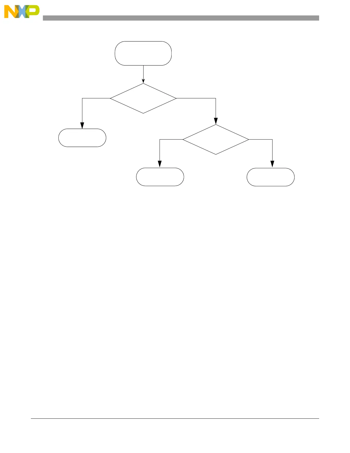
Figure 5-1. Boot mode selection
5.1.1 Flash memory boot
In order to sucessfully boot from flash memory, you must program two 32-bit fields into one of 5 possible
boot blocks as detailed below. The entities to program are:
• 16-bit Reset Configuration Half Word (RCHW), which contains:
— A BOOT_ID field that must be correctly set to 0x5A in order to "validate" the boot sector
• 32-bit reset vector (this is the start address of the user code)
The location and structure of the boot sectors in flash memory are shown in Figure 5-2.
FAB (PA[9]) value?
FAB = 0
Boot from
ABS (PA[8]) value?
Serial boot
(FlexCAN)
SSCM reads latched
values of PA[8] and
PA[9] pins
flash memory
Serial boot
(LINFlex)
FAB = 1
ABS = 0 ABS = 1