MPC5604B/C Microcontroller Reference Manual, Rev. 8
Freescale Semiconductor 587
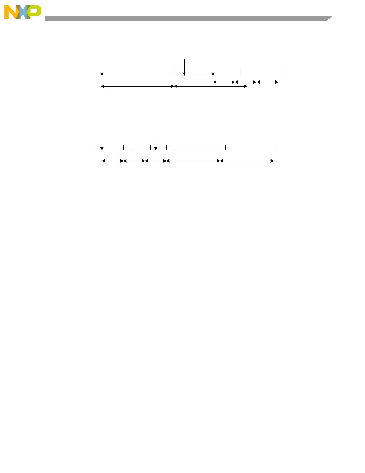
Figure 24-63. Modifying running timer period
Figure 24-64. Dynamically setting a new load value
24.5.5.1.2 Debug mode
In Debug mode the timers will be frozen. This is intended to aid software development, allowing the
developer to halt the processor, investigate the current state of the system (for example, the timer values)
and then continue the operation.
24.5.5.2 Interrupts
All of the timers support interrupt generation. See the INTC chapter of the reference manual for related
vector addresses and priorities.
Timer interrupts can be disabled by setting the TIE bits to zero. The timer interrupt flags (TIF) are set to 1
when a timeout occurs on the associated timer, and are cleared to 0 by writing a 1 to that TIF bit.
24.5.6 Initialization and application information
24.5.6.1 Example configuration
In the example configuration:
• The PIT clock has a frequency of 50 MHz
• Timer 1 creates an interrupt every 5.12 ms
• Timer 3 creates a trigger event every 30 ms
First the PIT module needs to be activated by programming PIT_MCR[MDIS] = 0.
The 50 MHz clock frequency equates to a clock period of 20 ns. Timer 1 needs to trigger every
5.12 ms/20 ns = 256000 cycles and Timer 3 every 30 ms/20 ns = 1500000 cycles. The value for the
LDVAL register trigger would be calculated as (period / clock period) – 1.
p1
Timer Enabled
Disable
Timer,
Start Value = p1
Trigger
Event
Re-Enable
Timer
p1
Set new
Load Value
p2 p2 p2
p1p1
Timer Enabled New Start
Value p2 set
p1 p2
Start Value = p1
p2
Trigger
Event