MPC5604B/C Microcontroller Reference Manual, Rev. 8
Freescale Semiconductor 219
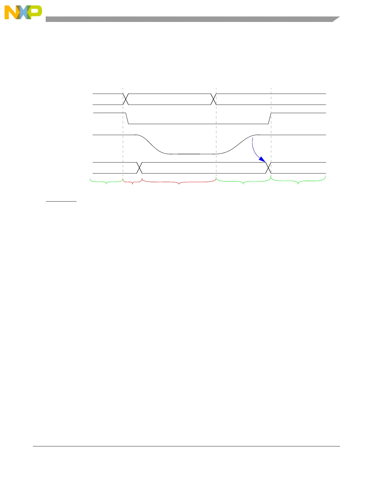
When the MC_PCU receives the mode change request to HALT mode, it starts its power-down phase.
During the power-down phase, clocks are disabled and the reset is asserted resulting in a loss of all
information for this power domain.
Then the power domain is disconnected from the power supply (power-down state).
When the MC_PCU receives a mode change request to RUN0, it starts its power-up phase if
PCU_PCONF2.RUN0 is ‘1’. The power domain is re-connected to the power supply, and the voltage in
power domain #2 will increase slowly. Once the voltage of power domain #2 is within an operable range,
its clocks are enabled, and its resets are deasserted (power-up state).
NOTE
It is possible that, due to a mode change, power-up is requested before a
power domain completed its power-down sequence. In this case, the
information in that power domain is lost.
10.4.4.2 STANDBY Mode Transition
STANDBY offers the maximum power saving. The level of power saving is software-controllable via the
settings in the PCU_PCONFn registers for power domain #2 onwards. Power domain #0 stays connected
to the power supply while power domain #1 is disconnected from the power supply. Amongst others power
domain #1 contains the platform and the MC_ME. Therefore this mode differs from all other user/system
modes.
Once STANDBY is entered it can only be left via a system wakeup. On exiting the STANDBY mode, all
power domains are powered up according to the settings in the PCU_PCONFn registers, and the DRUN
mode is entered. In DRUN mode, at least power domains #0 and #1 are powered.
new mode
power-down
RUN0
voltage in
PSTAT.PD2
HALT
RUN0
Notes:
Not drawn to scale; PCONF2.RUN0 = 1; PCONF2.HALT = 0
current mode
power-up phase
power domain #2
RUN0 HALT
RUN0
requested by ME
power-down state
power-up state
power-up state
phase
Figure 10-6. MC_PCU Events During Power Sequences (non-STANDBY mode)