Site Preparation and Installation
40
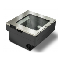
Magellan™ 9800i Scanner
Optional Remote Display Scale Diagnostics Indications
If your unit is equipped with an optional Remote Display, it will show the following sequence,
with each character being separated by a500ms or greater blank time on the display (for ease of
reading). This display continues to scroll across the display until the scanner changes state or is
reset.
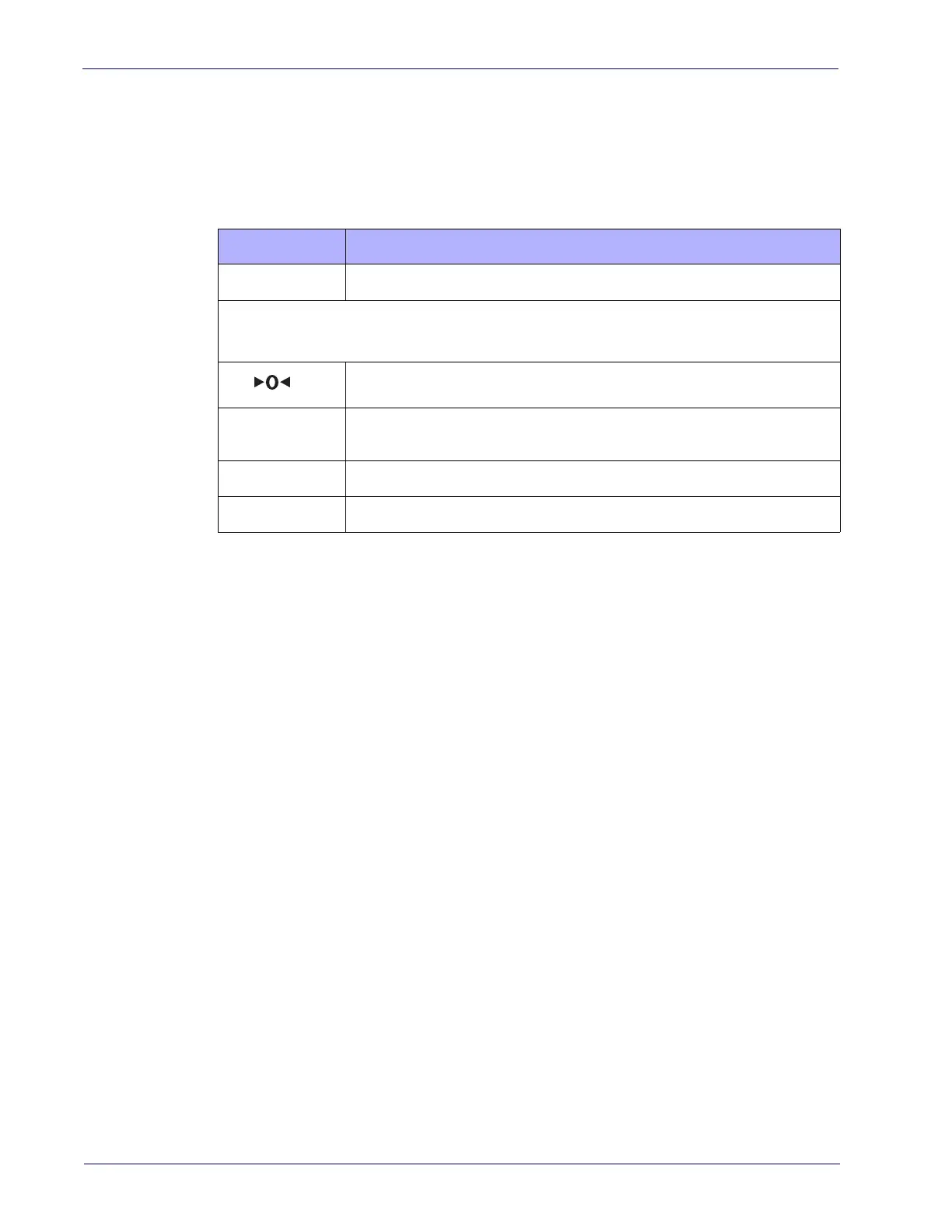
Table 4. Scale Diagnostic Remote Display Indications
CHARACTERS
EXPLANATION OF INDICATION
PASS or ERRx
Where x is 1 through 5.
All segments on the display are illuminated.
Where x indicates the number of scale zeroing attempts.
c x
Where xx represents the number of calibrations, with a maximum of 999
displayed.
— x
Where x indicates the scale gravity zone.
xxxx
Where xxxx is the load cell software checksum in hex lower 4 characters.
Cables & Connections
Considerations when routing the power and interface cables for the scanner and scanning-scale
are:
• Ensure that cables are not pinched, kinked or pierced.
• Do not route interface cables in close proximity
to electrical motors or other sources of
electromagnetic interference.
• Cables can drop directly from their connectors on the scanner
, or, alternatively, can be
routed along the scanner’s side to the back (see
Figure 25).
Do not plug the AC power cord into the outlet at
this time. It is a good practice to always
connect the power cable to the scanner first before plugging it into the AC receptacle. The
procedures titled, Set-Up, provided later in this section will instruct you to connect the power
cord at that time.
Figure 25 illustrates the basic cable routing scheme.

 Loading...