MPC5604B/C Microcontroller Reference Manual, Rev. 8
230 Freescale Semiconductor
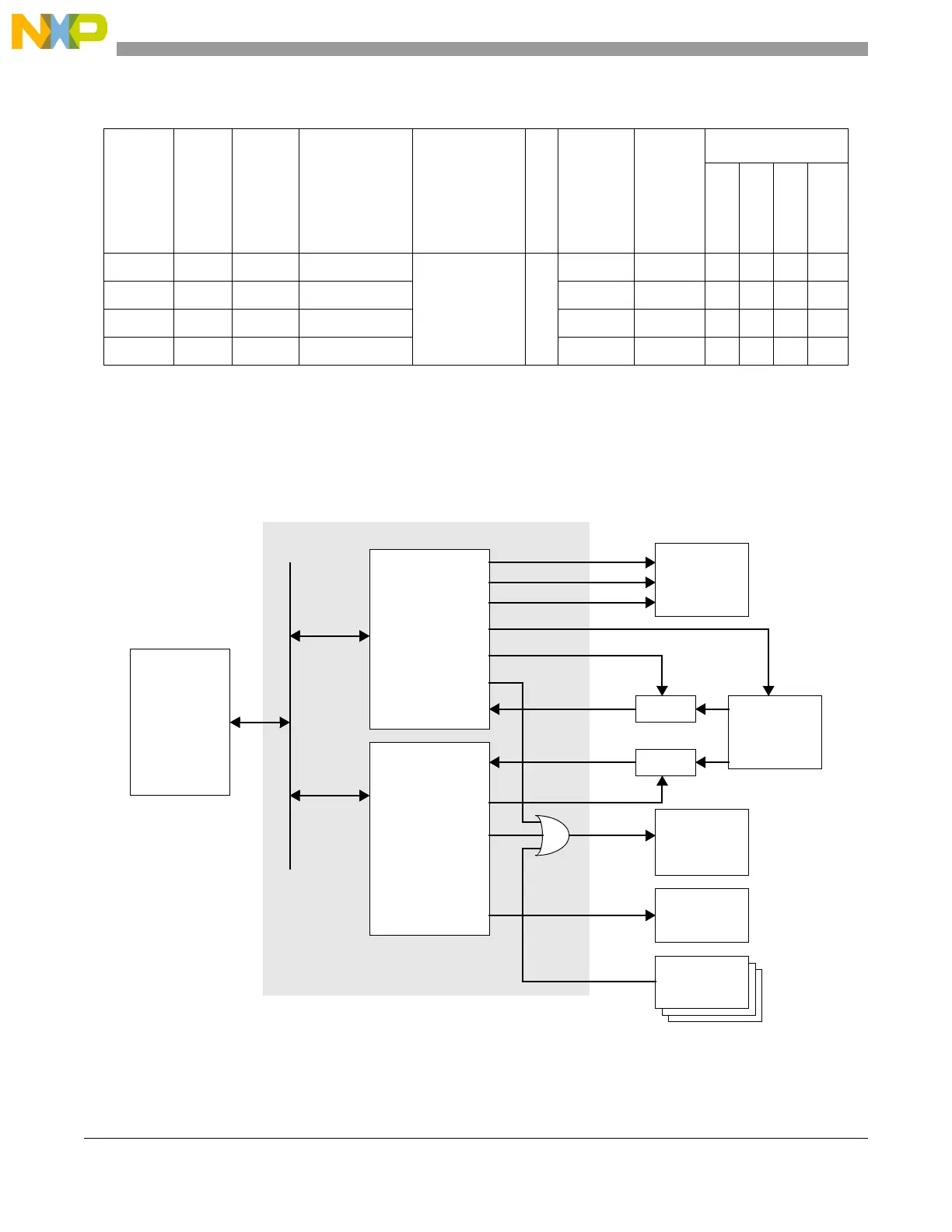
Figure 12-1. WKPU block diagram
WKPU16 PF13 PCR93 — WakeUp_IRQ_2 48 EIF16 15 x
4
x
4
WKPU17 PG3 PCR99 — EIF17 14 x
4
x
4
WKPU18 PG5 PCR101 — EIF18 13 x
4
x
4
WKPU19 PA0 PCR0 — EIF19 12
1
This column does not contain an exhaustive list of functions on that pin. Rather, it includes peripheral communication
functions (such as CAN and LINFlex Rx) that could be used to wake up the microcontroller. DSPI pins are not included
because DSPI would typically be used in master mode.
2
WISR, IRER, WRER, WIFEER, WIFEEF, WIFER, WIPUER
3
Port not required to use timer functions.
4
Unavailable WKPU pins must use internal pullup enabled using WIPUER.
Table 12-1. Wakeup vector mapping (continued)
Wakeup
number
Port
SIU
PCR#
Port input
function
1
(can
be used in
conjunction
with WKPU
function)
WKPU IRQ to
INTC
IRQ#
WISR
Register
2
bit
position
Package
64-pin QFP
100-pin QFP
144-pin QFP
208-pin BGA
IPS
BUS
Pads
Interrupt
Controller
Peripheral
Mode /
Power Control
IRQs
system wakeup
wakeup
0-19
Platform
0-2
NMI / Wakeup
- Configuration
IRQ / Wakeup
- Configuration
Wakeup Unit
IOMux
RTC, etc.
0-19
filter
filter
filter bypass
filter bypass
NMI enable
Bridge