MPC5604B/C Microcontroller Reference Manual, Rev. 8
20 Freescale Semiconductor
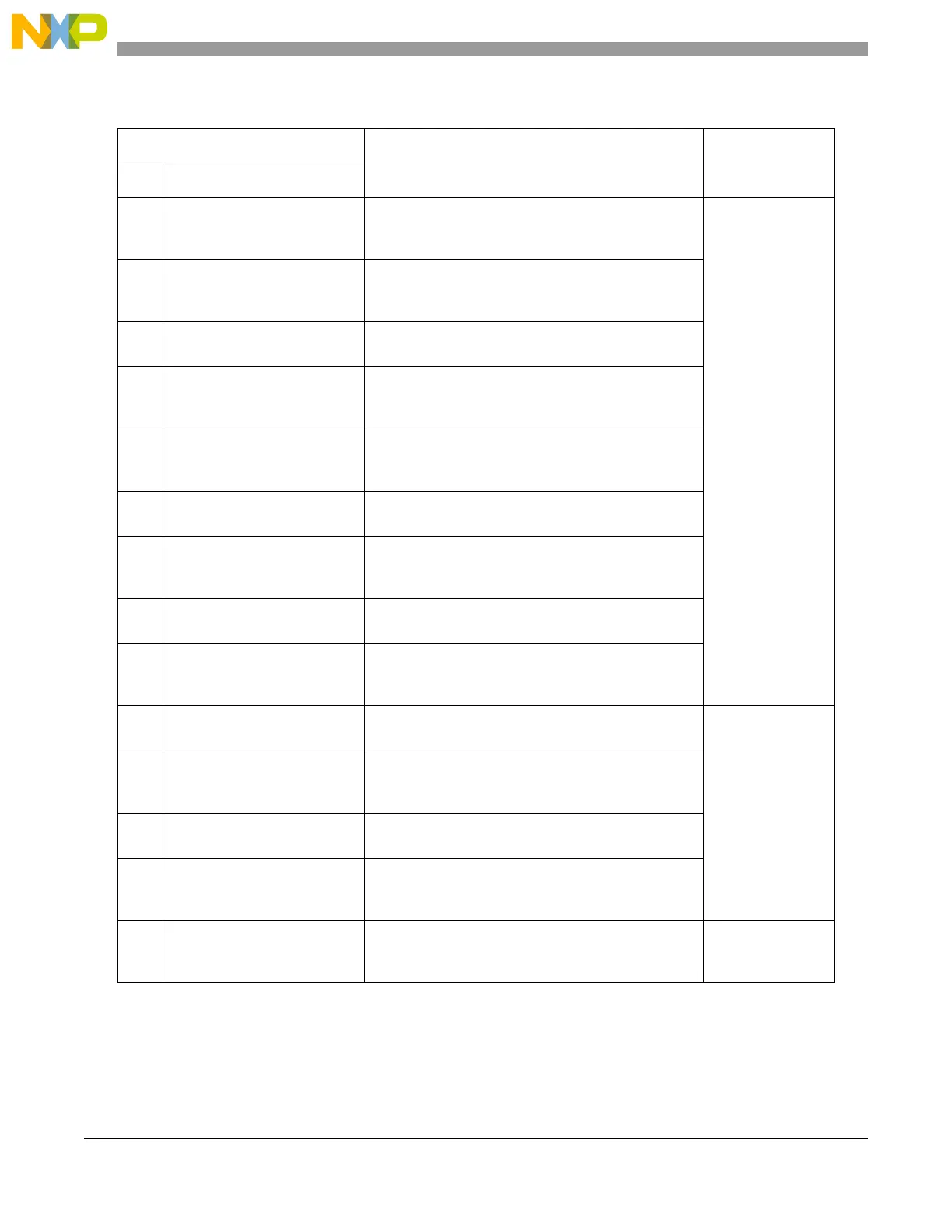
6 Clock Description • Covers configuration of all of the clock sources in
the system.
• Describes the Clock Monitor Unit (CMU).
Clocks and power
(includes operating
mode configuration
and how to wake up
from low power
mode)
7 Clock Generation Module
(MC_CGM)
Determines how the clock sources are used (including
clock dividers) to generate the reference clocks for all
of the modules and peripherals.
8 Mode Entry Module (MC_ME) Determines the clock source, memory, power and
peripherals that are available in each operating mode.
9 Reset Generation Module
(MC_RGM)
Manages the process of entering and exiting reset,
allows reset sources to be configured (including
LVD's) and provides status reporting.
10 Power Control Unit (MC_PCU) Controls the power to different power domains within
the microcontroller (allowing SRAM to be selectively
powered in STANDBY mode).
11 Voltage Regulators and Power
Supplies
Information on voltage regulator implementation.
Includes enable bit for 5 V LVD (see also MC_RGM).
12 Wakeup Unit (WKPU) Always-active analog block. Details configuration of 2
internal (API/RTC) and 30 external (pin) low power
mode wakeup sources.
13 Real Time Clock / Autonomous
Periodic Interrupt (RTC/API)
Details configuration and operation of timers that are
predominately used for system wakeup.
14 CAN Sampler Details on how to configure the CAN sampler which is
used to capture the identifier frame of a CAN message
when the microcontroller is in low power mode.
15 e200z0h Core Overview on cores. For more details consult the core
reference manuals available on www.freescale.com.
Core platform
modules
16 Interrupt Controller (INTC) Provides the configuration and control of all of the
external interrupts (non-core) that are then routed to
the IVOR4 core interrupt vector.
17 Crossbar Switch (XBAR) Describes the connections of the XBAR masters and
slaves on this microcontroller.
18 Memory Protection Unit (MPU) The MPU sits on the slave side of the XBAR and
allows highly configurable control over all master
accesses to the memory.
19 System Integration Unit Lite
(SIUL)
How to configure the pins or ports for input or output
functions including external interrupts and DSI
serialization.
Ports
Table 1-1. Guide to this reference manual (continued)
Chapter
Description Functional group
#Title