MPC5604B/C Microcontroller Reference Manual, Rev. 8
Freescale Semiconductor 393
21.7.1.5 UART mode control register (UARTCR)
FEF Framing Error Flag
This bit is set by hardware and indicates to the software that LINFlex has detected a framing error
(invalid stop bit). This error can occur during reception of any data in the response field (Master or
Slave mode) or during reception of Synch Field or Identifier Field in Slave mode.
BOF Buffer Overrun Flag
This bit is set by hardware when a new data byte is received and the buffer full flag is not cleared. If
RBLM in LINCR1 is set then the new byte received is discarded. If RBLM is reset then the new byte
overwrites the buffer. It can be cleared by software.
NF Noise Flag
This bit is set by hardware when noise is detected on a received character. This bit is cleared by
software.
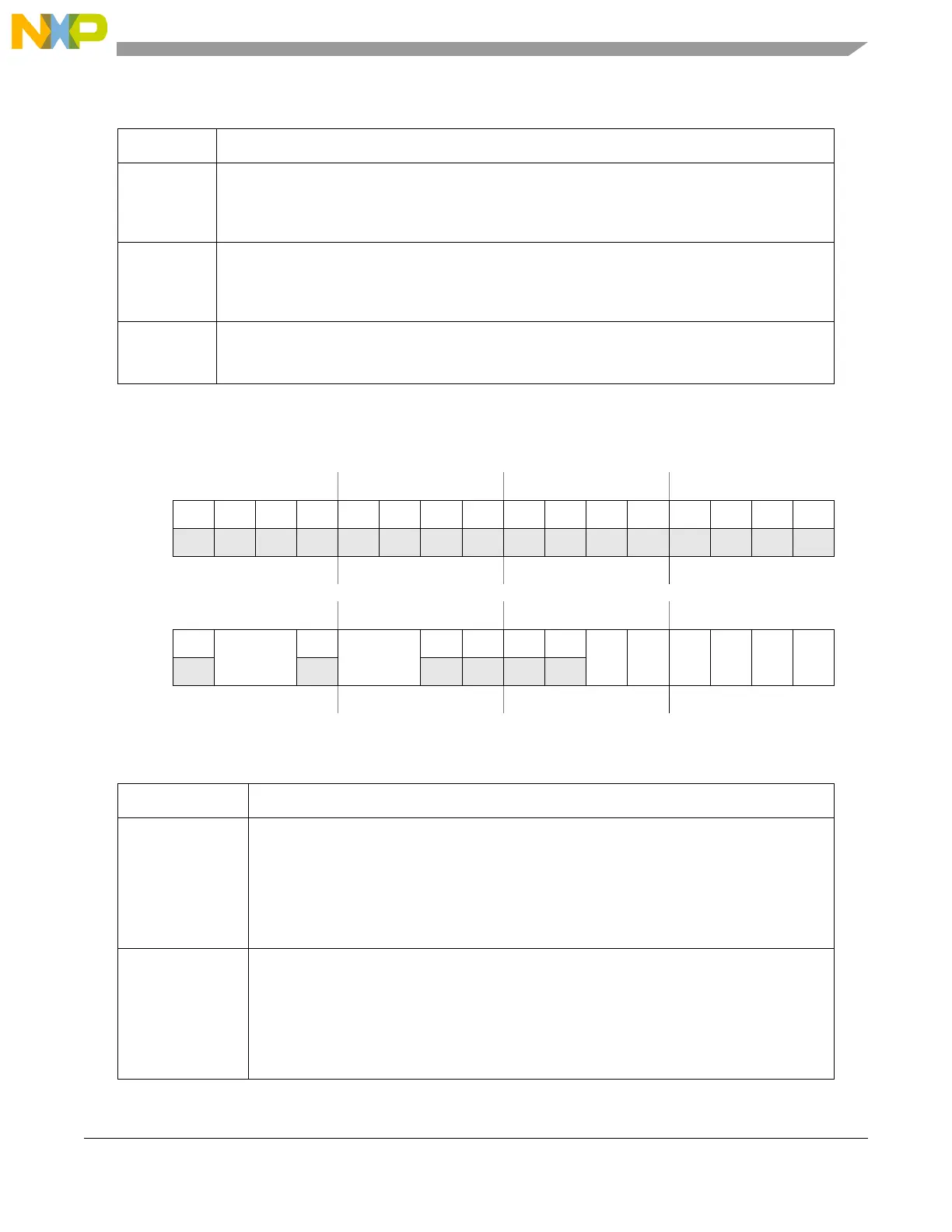
Offset: 0x0010 Access: User read/write
0123456789101112131415
R 0000000000000000
W
Reset0000000000000000
16 17 18 19 20 21 22 23 24 25 26 27 28 29 30 31
R 0
TDFL
0
RDFL
0000
RXEN
TXEN
OP PCE WL
UART
W
Reset0000000000000000
Figure 21-10. UART mode control register (UARTCR)
Table 21-10. UARTCR field descriptions
Field Description
TDFL Transmitter Data Field length
This field sets the number of bytes to be transmitted in UART mode. It can be programmed only
when the UART bit is set. TDFL[0:1] = Transmit buffer size – 1.
00 Transmit buffer size = 1.
01 Transmit buffer size = 2.
10 Transmit buffer size = 3.
11 Transmit buffer size = 4.
RDFL Receiver Data Field length
This field sets the number of bytes to be received in UART mode. It can be programmed only
when the UART bit is set. RDFL[0:1] = Receive buffer size – 1.
00 Receive buffer size = 1.
01 Receive buffer size = 2.
10 Receive buffer size = 3.
11 Receive buffer size = 4.
Table 21-9. LINESR field descriptions (continued)
Field Description