MPC5604B/C Microcontroller Reference Manual, Rev. 8
Freescale Semiconductor 555
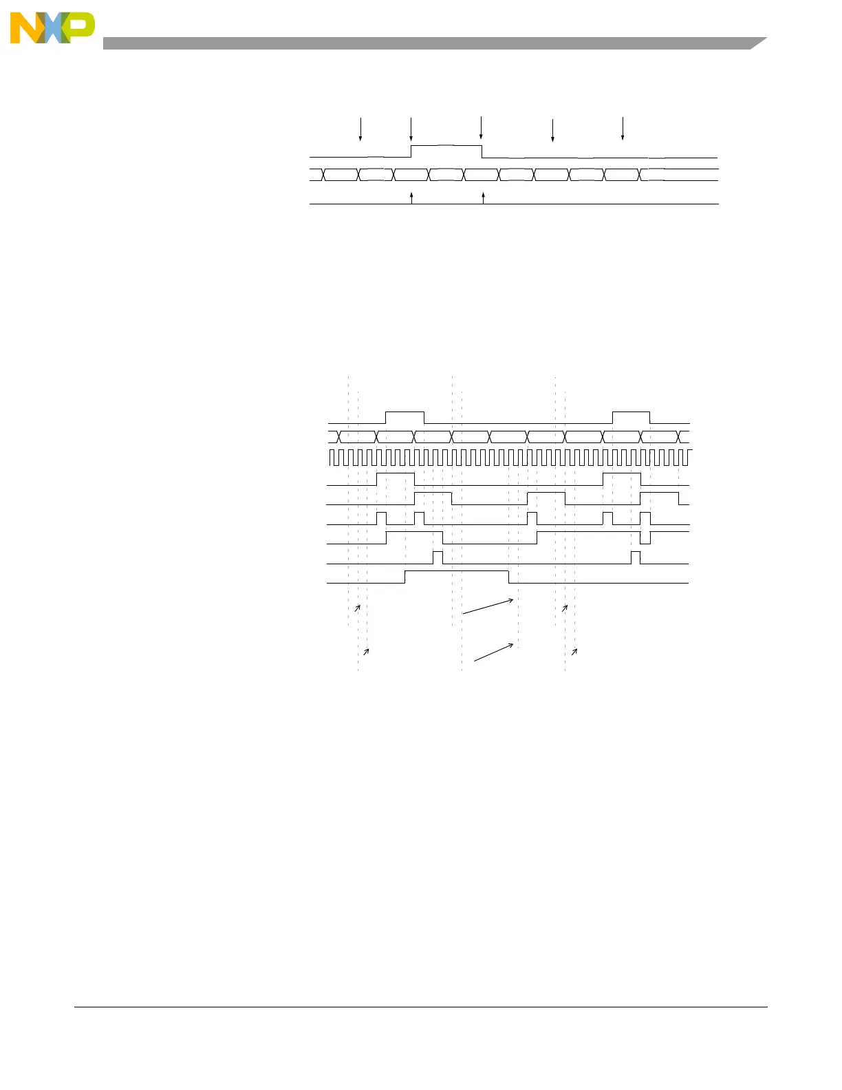
Figure 24-28. Double action output compare with FLAG set on both matches
Figure 24-29. DAOC with transfer disabling example
24.4.4.1.1.7 Modulus Counter (MC) mode
The MC mode can be used to provide a time base for a counter bus or as a general purpose timer.
Bit MODE[6] selects internal or external clock source when cleared or set, respectively. When external
clock is selected, the input signal pin is used as the source and the triggering polarity edge is selected by
the EDPOL and EDSEL in the EMIOSC[n] register.
The internal counter counts up from the current value until it matches the value in register A1. Register B1
is cleared and is not accessible to the MCU. Bit MODE[4] selects up mode or up/down mode, when cleared
or set, respectively.
selected counter bus 0x000500 0x001000 0x001100 0x001000 0x001100
A1 value
1
B1 value
2
0xxxxxxx 0x001100 0x001100 0x001100
0xxxxxxx 0x001000 0x001000 0x001000
output flip-flop
A1 match
B1 match
Update to
A1 and B1
FLAG pin/register
A1 match
B1 match
Notes:
1. EMIOSA[n] = A1 (when reading)
2. EMIOSB[n] = B1 (when reading)
A2 = A1according to OU[n] bit
B2 = B1according to OU[n] bit
MODE[6] = 1
selected counter bus 0x0 0x2
FLAG set event
A1 value
2
0xx
output flip-flop
2. EMIOSA[n] = A1 (when reading)
0x0 0x20x1 0x2 0x0 0x10x1
FLAG pin/register
FLAG clear
EDSEL = 1
System Clock
enabled A1 match
EDPOL = x
B2 value
5
0x2
B1 value
4
0xx
A2 value
3
0x1
OU
1
enabled B1 match
0x1
0xx
0xx
0x2
0x1
write to A2
0x2
0x2
0x1
0x2
0x1
0x1
0x2
write to B2
write to A2
write to B2
write to A2
write to B2
MODE[0]=1
3. EMIOSA[n] = A2 (when writing)
4. EMIOSB[n] = B1 (when reading)
5. EMIOSB[n] = B2 (when writing)
Note: 1. OU[n] bit of EMIOSOUDIS register