MPC5604B/C Microcontroller Reference Manual, Rev. 8
574 Freescale Semiconductor
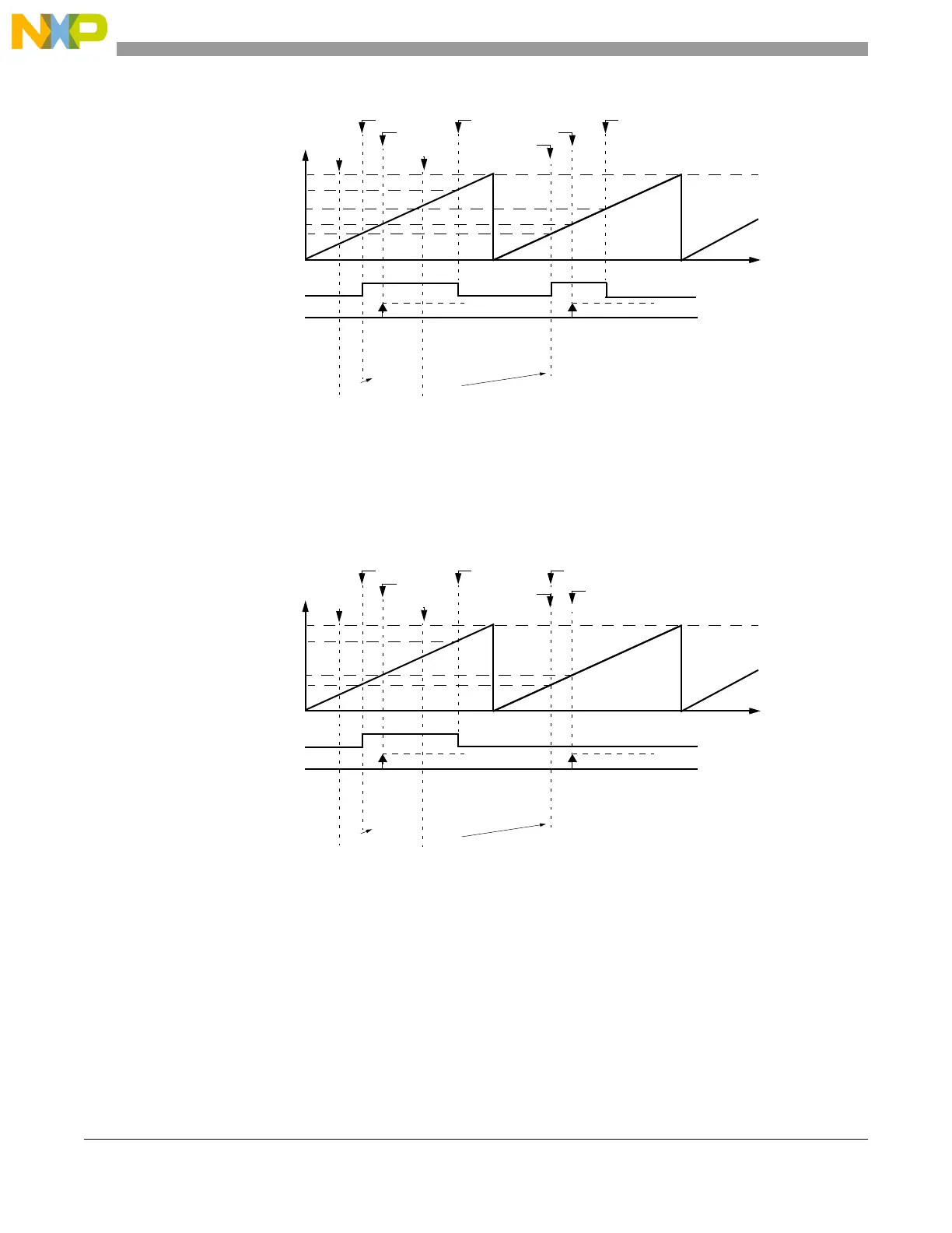
Figure 24-47. OPWMT example
Figure 24-48 shows the Unified Channel running in OPWMT mode with Trigger Event Generation and
0% duty.
Figure 24-48. OPWMT with 0% Duty Cycle
Figure 24-49 shows the Unified Channel running in OPWMT mode with Trigger Event Generation and
100% duty cycle.
0x0011FF
0x001000
0x000000
selected counter bus
Time
output flip-flop
A1 value
1
write to B2
0x000400
B1 value
B2 value
2
0x000700
Match B1
write to A1
0xxxxxxx
0x000400
0x001000
0x000700
and B2
0x001000
Match A1
Match B1 Match A1
Notes:
1. EMIOSA[n] = A1
2. EMIOSB[n] = B2 for write, B1 for read
0x000700
Notes:
A2 value
0x000500
0x000500
FLAG pin/register
Match A2
Match A2
0x0011FF
0x001000
0x000000
selected counter bus
Time
output flip-flop
A1 value
1
write to B2
0x000400
B1 value
B2 value
2
0x000400
Match B1
write to A1
0xxxxxxx
0x000400
0x001000
and B2
0x001000
Match A1
Match B1 Match A1
Notes:
1. EMIOSA[n] = A1
2. EMIOSB[n] = B2 for write, B1 for read
0x000400
Notes:
A2 value
0x000500
0x000500
FLAG pin/register
Match A2
Match A2
 Loading...