Mixer : Mixer Delay Compensation
10 - 244
Delay Compensation of External Inputs
Where an Output Bus is used to feed an external processor via a physical output and the external processor output
is fed back into Pyramix via an external live input, then the necessary delay compensation must be computed and
applied by the operator since Pyramix has no means of determining the delay of the external device. However, the
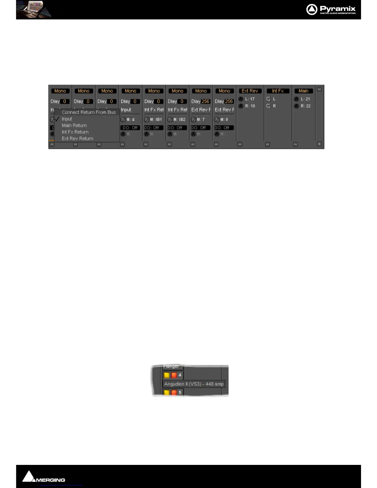
Input Strip Mode (Click on
Input to pop-up the menu) should be set to the bus feeding the external processor (as
above) so that the input channel delay setting affects delay compensation rather than simply delaying the signal
through the input strip.
In the illustration, Group Bus
Ext Rev feeds an external device via physical outputs 17 & 18. The outputs of the
external device are connected to physical inputs
7 & 8. The channels’ Mode has been set to Ext Rev Return and
delay compensation of
256 samples applied.
In contrast
Int FX SubGroup bus has VS3 and VST plug-ins inserted in the strip and feeds the output buses
directly. There is, of course, no reason why an external insert cannot be used in a SubGroup instead of using an
Output bus for this purpose.
External Insert Plug-ins
Internal VS3 Engine latency is automatically compensated except for the daughter card I/O latency (for example a
Send/Return on AES/EBU takes 6 samples). Thus you have to manually set the delay of the external unit plus the I/
O latency. It is not possible to change the delay or change the bypass status during playback or recording.
Determining Delay Compensation for External Effects Loops
One strategy for achieving this is to route a signal directly to an Output Bus and, via a physical output from a sec-
ond Output Bus, to the external processor’s input. The processor’s output is connected to a physical Pyramix input
and routed to an input strip. The strip mode must be set to the Bus used as the source. Then you can use impulse
sounds, clicks, rimshots etc. to aid manual adjustment of the delay compensation by comparing the direct sound
with the sound returning from the external processor.
Determining Delay Compensation for External Insert Plug-ins
A similar strategy can be employed here. Route the signal you wish to treat with an External Insert Plug-in to two
input strips. Add the External Insert in one strip only, complete with the external processor in circuit. Delay the
untreated strip until the audio is in sync with the treated audio and note the delay value. Then apply this value in
the
Ext. Unit Delay field in the External Insert window.
Effects Delay Indication
When the mouse cursor is hovered over a plug-in, in a strip, the required delay value is displayed:
Here you can see that
Angudion II currently requires a 448 sample delay to be applied to the other output buses.
This will be applied automatically when
Full Delay Compensation is switched on.