Settings : Mixer
28 - 662
Headroom
Sets the amount of headroom displayed as red meter segments before clipping. I.e. the num-
ber of dB below 0dBFs at which the red meter segments begin.
Note: This headroom value is only for the Mixer meter displays and will not (and
cannot) be reported to the Plug-in (VU Meter or Meter Bridge). The VU meter
Plug-in has it’s own headroom setting.
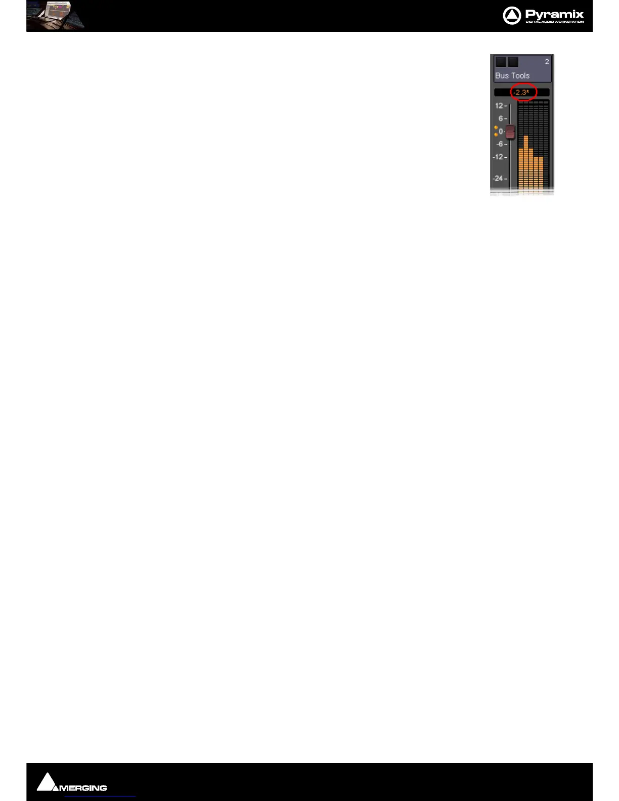
Note: If the mixer displays an * next to the Level field value it indicates that a cus-
tom value was entered in the Headroom settings.
Alignment
Sets the alignment level. Displayed by the point on the scale at which the dark orange seg-
ments begin.
Peak and Overload Hold Time
Sets the amount of time in seconds that the peak segment or overload segment (topmost red segment) of the
level meter remains illuminated.
Permanent Overload
When the box is checked, the red Overload LED above a Track will remain lit, even after playback is stopped. To
clear the LED, double-click it. When not checked, the Overload LED will automatically clear itself after a few sec-
onds and remain off until the next overload occurrence.
Note: The overload LED will go on after one sample with the maximum level.
Permanent Peak
This parameter works in conjunction with the Peak Level Display. When this is on (checked), the Peak Level pop-up
display will show the value and location of the highest level reached on a Track up to the time when the mouse
was clicked on the meter. The level display will not be updated until the next time playback is stopped and re-
started. If it is not on (unchecked), the Peak Level Popup Display will show the highest level reached in that Track
from the last time the Popup Display is activated (while playback continues). For example, clicking a channel’s
meter while playing back will display the Peak Level Popup, which will show the peak level (and its location)
reached so far. Click away from the Popup, and it will disappear. Click on that meter again, and the Popup will
appear again, this time showing the peak level/location reached since the last time the Popup was displayed.
Decay integration time
This parameter sets the rate at which the level meter display decays after the level falls below the most recent
peak. The slope of the decay is given in terms of milliseconds per decibel (ms/dB).
Peak level indicator
Show After
When the box is checked, the Fader/Input Level displays located above the faders on each mixer strip display the
peak level of the signal running through the corresponding mixer strip. The value are updated at the interval set
by the slider below the check box. If the check box
Show After is off, the Fader/Input Level displays always show
the setting of their corresponding fader.
DSD Peak Filter
For DSD projects this drop-down list offers the choice between two filtering options which will be applied to the
DSD signal before it is measured by the level meter.
This will help enable you to ensure that the DSD signal is compatible with the AES recommendations concerning
the high frequency dither noise content.
20k
Applies a 20 kHz low pass filter to the signal, thus only the audible audio content is measured.
40k-100k