Appendices : Appendix II Legacy Mykerinos I/O Daughter-card Options
30 - 727
Appendix II Legacy Mykerinos I/O Daughter-card Options
ADAT Optical I/O
The ADAT Optical daughter card offers 16 channels of audio input and 16 channels of audio output, 8 channels per
optical connection. From top to bottom of the card, it has two digital optical input connectors (Inputs A and B) and
two digital optical output connectors (Outputs A and B).
The signal format of optical connectors Input A and Output A can be set inside the Pyramix software to operate in
either ADAT or S/PDIF mode. When in ADAT mode, there are 8 discrete audio channels carried per each optical
connector. S/PDIF mode has 2 channels per optical connector.
Note: in SPDIF mode the maximum sampling rate is limited to 48 kHz
Note that whilst the ADAT daughterboard continues to function normally in HDTDM (64 bus) mode it cannot be
used for input when in XDTDM (128 bus) mode and is only capable of 8 outputs via Optical Output A with the
same 8 duplicated on Optical Output B.
WARNING! The ADAT Daughterboard requires modification before attempting to use it with XDTDM mode. Fail-
ure to do this may result in data loss. Please contact your Merging Technologies Sales Partner to arrange a mod.
AES/EBU I/O
The AES/EBU daughter card offers 24 channels of I/O over 12 AES/EBU input and output pairs. Connection is via
three DB-25 connectors, One on the main card attached to the
Mykerinos and two more on a separate bracket
connected via internal ribbon cable to the main card. An optional break-out cable can be ordered separately
which connects to the DB-25 connector and terminates in 8 XLR connectors which may be used to connect to
standard AES/EBU stereo inputs and outputs. AES daughter cards are available with or without 8 channels of SRC
(sample rate conversion)
AES II with SRC
The AES II daughter card is equipped with 4 unidirectional SRC chips. Each one can be configured as bypass, input
or output. On a specific in/out channel pair a sampling rate conversion can be applied only in one direction, either
input or output. The "Speed on physical wire" setting should be set to the project's sampling rate (aka "single-wire
mode") whenever the SRCs are used, since channel pairs that are spread over several wires will not be sample rate
converted properly. In
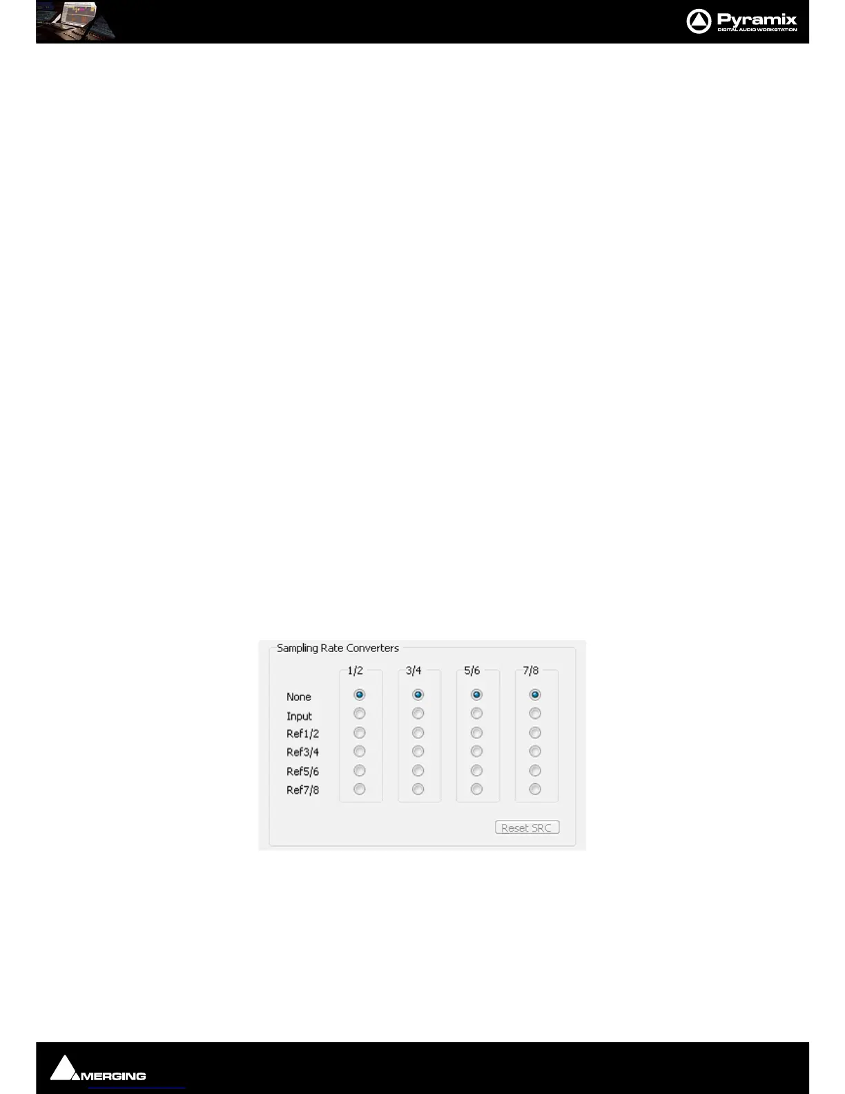
Settings > All Settings > Hardware > I/O Interfaces, the I/O interface page corresponding
to each AES II daughter card in the system shows an array like this:
Up to 192 kHz, each column represents one XLR connector (one pair of channels) with its associated SRC chip.
The following configurations can be selected:
•
None: or bypass, the SRC is transparent
•
Input: The SRC works on the input path and converts the incoming signal to the project's sampling rate
•
Ref1/2 through Ref 7/8: The SRC is inserted in the output path and converts the output signal to the sam-
pling rate of the signal present at the input chosen as reference.