Product Reference Guide
19
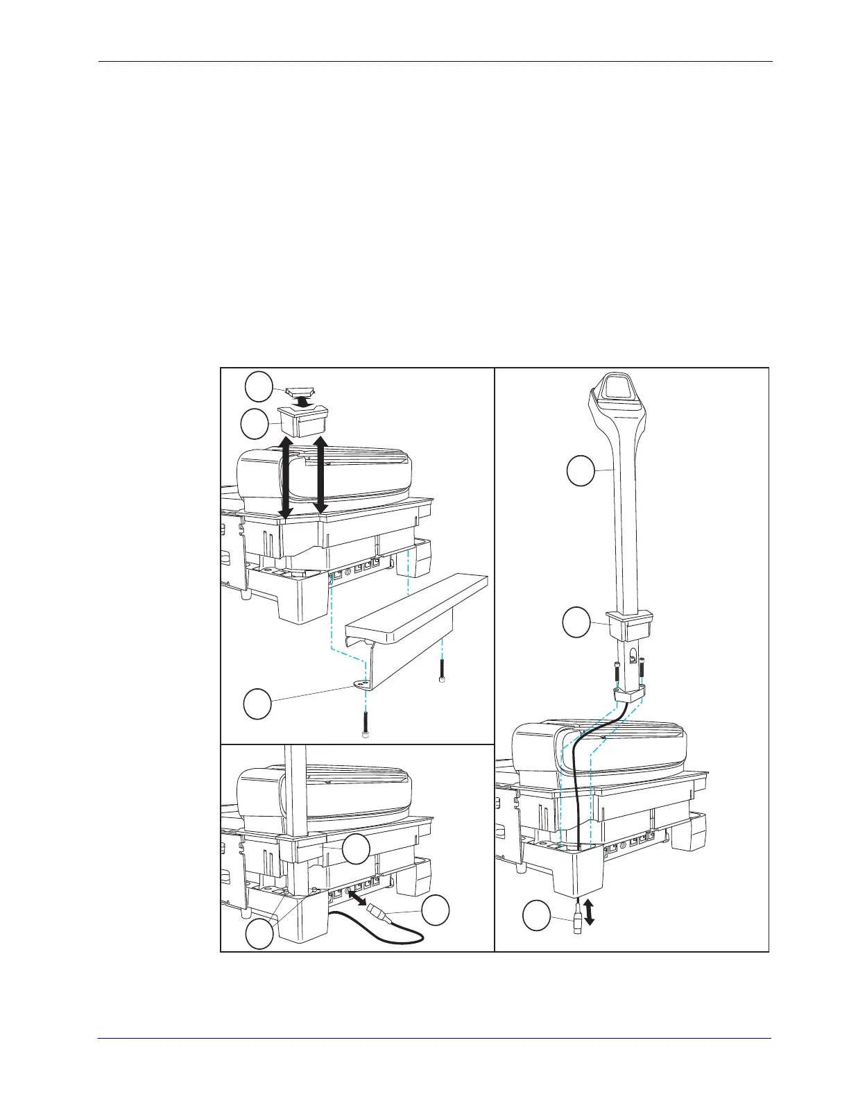
6. Route the TDR cable down through the base of the scanner (Figure 9, #6), gently pulling
it all the way through on the bulkhead side of
the base and seating the TDR in its corner
cavity. Make sure it is not pinched or caught beneath the scanner base.
7. Use a 3mm ball end hex driver to secure the TDR with the two bolts provided for this
purpose (
Figure 9, #7), tightening them evenly to 1.74Nm (15 in-lb).
8. Fully seat the plastic Corner Piece in the grooves intended for it on the scanner frame
(
Figure 9, #8).
9. Verify that the cable is not pinched or caught be
tween assemblies, then connect it to its 8-
pin Din connection in the center of the bulkhead (
Figure 9, #9).
10. [Long Scanner/Scale models ONLY] S
ecure the Back Flange Assembly (Figure 9, #1) to
the Scanner/Scale using the original bolts. Tig
hten both evenly to 0.79 Nm (7 in-lb).
Figure 9. Installing the Optional TDR

 Loading...