MPC5604B/C Microcontroller Reference Manual, Rev. 8
Freescale Semiconductor 359
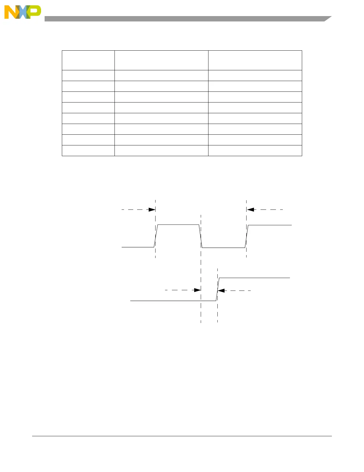
The number of clocks from the falling edge of SCL to the first tap (Tap[1]) is defined by the values shown
in the scl2tap column of Table 20-5. All subsequent tap points are separated by 2
IBC5-3
as shown in the
tap2tap column in Table 20-5. The SCL Tap is used to generate the SCL period and the SDA Tap is used
to determine the delay from the falling edge of SCL to the change of state of SDA i.e. the SDA hold time.
Figure 20-4. SDA hold time
Table 20-6. I-Bus tap and prescale values
IBC2-0
SCL Tap
(clocks)
SDA Tap
(clocks)
000 5 1
001 6 1
010 7 2
011 8 2
100 9 3
101 10 3
110 12 4
111 15 4
SCL Divider
SDA Hold
SCL
SDA