MPC5604B/C Microcontroller Reference Manual, Rev. 8
396 Freescale Semiconductor
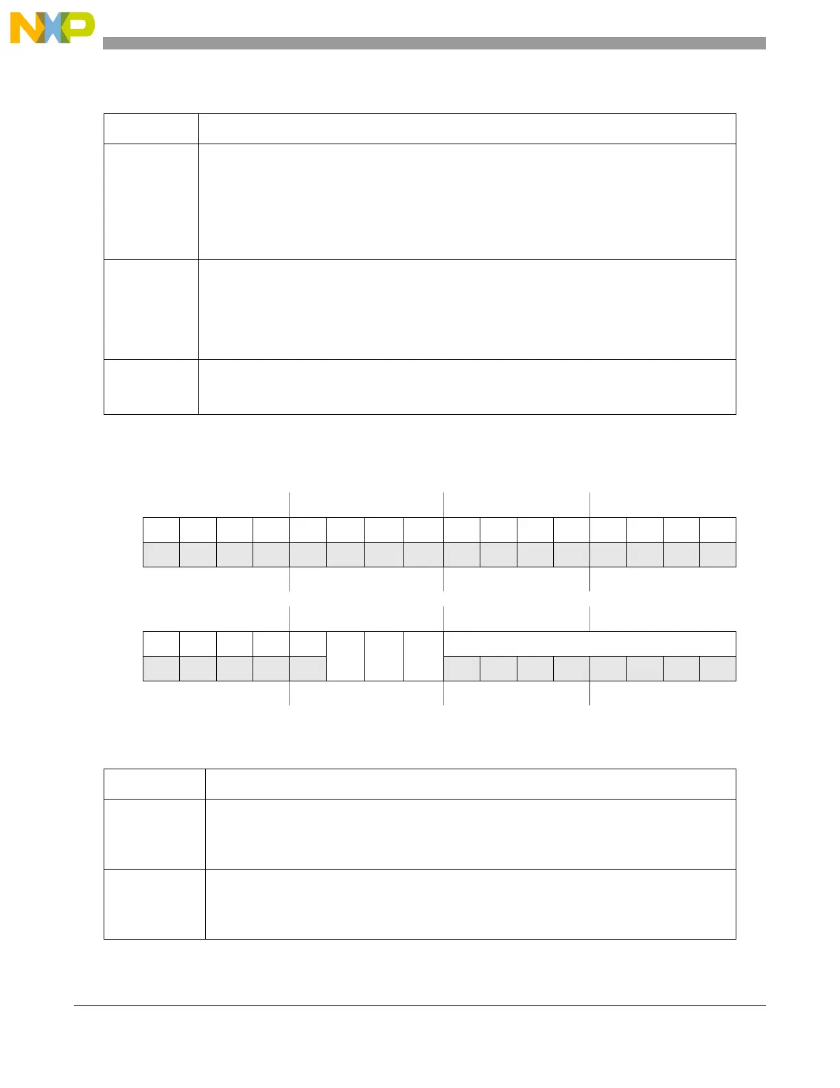
21.7.1.7 LIN timeout control status register (LINTCSR)
DRF Data Reception Completed Flag
This bit is set by hardware and indicates the data reception is completed, that is, the number of
bytes programmed in RDFL[0:1] in UARTCR have been received.
This bit must be cleared by software.
It is reset by hardware in Initialization mode.
An interrupt is generated if DRIE bit in LINIER is set.
Note: In UART mode, this flag is set in case of framing error, parity error or overrun.
DTF Data Transmission Completed Flag
This bit is set by hardware and indicates the data transmission is completed, that is, the number of
bytes programmed in TDFL[0:1] have been transmitted.
This bit must be cleared by software.
It is reset by hardware in Initialization mode.
An interrupt is generated if DTIE bit in LINIER is set.
NF Noise Flag
This bit is set by hardware when noise is detected on a received character. This bit is cleared by
software.
Offset: 0x0018 Access: User read/write
012345 6 7 89101112131415
R 0000000 000000000
W
Reset000000 0 0 00000000
16 17 18 19 20 21 22 23 24 25 26 27 28 29 30 31
R 00000
LTOM
IOT TOCE
CNT
W
Reset000000 1 0 00000000
Figure 21-12. LIN timeout control status register (LINTCSR)
Table 21-12. LINTCSR field descriptions
Field Description
LTOM LIN timeout mode
0 LIN timeout mode (header, response and frame timeout detection).
1 Output compare mode.
This bit can be set/cleared in Initialization mode only.
IOT Idle on Timeout
0 LIN state machine not reset to Idle on timeout event.
1 LIN state machine reset to Idle on timeout event.
This bit can be set/cleared in Initialization mode only.
Table 21-11. UARTSR field descriptions (continued)
Field Description