MPC5604B/C Microcontroller Reference Manual, Rev. 8
544 Freescale Semiconductor
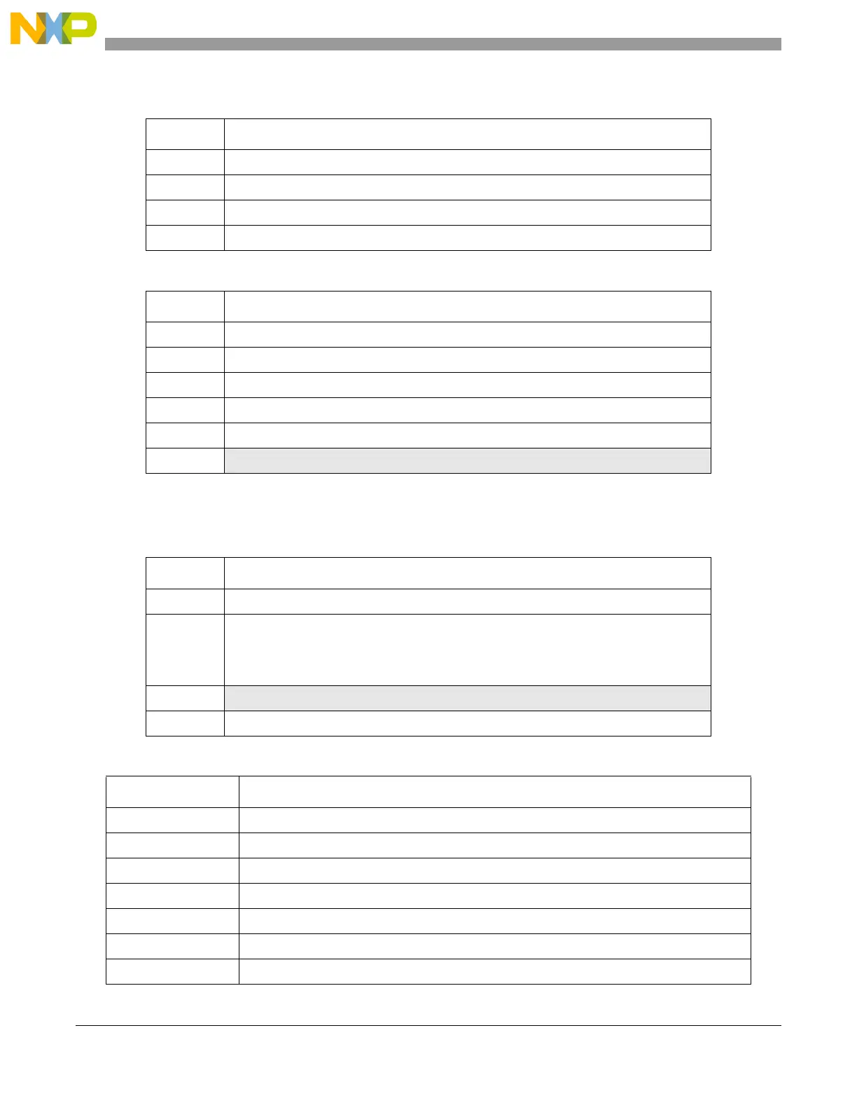
Table 24-18. UC internalprescaler clock divider
UCPRE Divide ratio
00 1
01 2
10 3
11 4
Table 24-19. UC input filter bits
IF
1
1
Filter latency is 3 clock edges.
Minimum input pulse width [FLT_CLK periods]
0000 Bypassed
2
2
The input signal is synchronized before arriving to the digital filter.
0001 02
0010 04
0100 08
1000 16
all others Reserved
Table 24-20. UC BSL bits
BSL Selected bus
00 All channels: counter bus[A]
01 Channels 0 to 7: counter bus[B]
Channels 8 to 15: counter bus[C]
Channels 16 to 23: counter bus[D]
Channels 24 to 27: counter bus[E]
10
Reserved
11 All channels: internal counter
Table 24-21. Channel mode selection
MODE
1
Mode of operation
0000000 General purpose Input/Output mode (input)
0000001 General purpose Input/Output mode (output)
0000010 Single Action Input Capture
0000011 Single Action Output Compare
0000100 Input Pulse Width Measurement
0000101 Input Period Measurement
0000110 Double Action Output Compare (with FLAG set on B match)