MPC5604B/C Microcontroller Reference Manual, Rev. 8
548 Freescale Semiconductor
It is required that when changing MODE[0:6], the application software goes to GPIO mode first in order
to reset the UC’s internal functions properly. Failure to do this could lead to invalid and unexpected output
compare or input capture results or the FLAGs being set incorrectly.
In GPIO input mode (MODE[0:6] = 0000000), the FLAG generation is determined according to EDPOL
and EDSEL bits and the input pin status can be determined by reading the UCIN bit.
In GPIO output mode (MODE[0:6] = 0000001), the Unified Channel is used as a single output port pin
and the value of the EDPOL bit is permanently transferred to the output flip-flop.
24.4.4.1.1.2 Single Action Input Capture (SAIC) mode
In SAIC mode (MODE[0:6] = 0000010), when a triggering event occurs on the input pin, the value on the
selected time base is captured into register A2. The FLAG bit is set along with the capture event to indicate
that an input capture has occurred. Register EMIOSA[n] returns the value of register A2. As soon as the
SAIC mode is entered coming out from GPIO mode the channel is ready to capture events. The events are
captured as soon as they occur thus reading register A always returns the value of the latest captured event.
Subsequent captures are enabled with no need of further reads from EMIOSA[n] register. The FLAG is set
at any time a new event is captured.
The input capture is triggered by a rising, falling or either edges in the input pin, as configured by EDPOL
and EDSEL bits in EMIOSC[n] register.
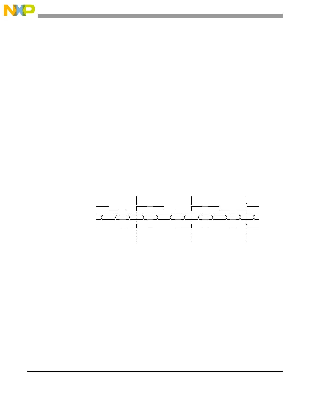
Figure 24-18 and Figure 24-19 show how the Unified Channel can be used for input capture.
Figure 24-18. Single action input capture with rising edge triggering example
selected counter bus 0x000500 0x001000 0x001100 0x001250 0x001525 0x0016A0
FLAG pin/register
A2 (captured) value
2
0xxxxxxx 0x001000 0x001250 0x0016A0
input signal
1
Edge detect Edge detect
Edge detect
Notes: 1. After input filter
2. EMIOSA[n] <= A2
EDSEL = 0
EDPOL = 1