MPC5604B/C Microcontroller Reference Manual, Rev. 8
Freescale Semiconductor 557
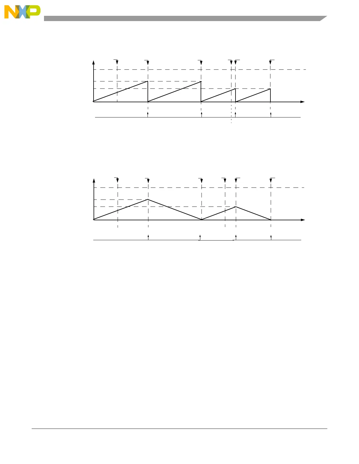
Figure 24-30. Modulus Counter Up mode example
Figure 24-31. Modulus Counter Up/Down mode example
24.4.4.1.1.8 Modulus Counter Buffered (MCB) mode
The MCB mode provides a time base which can be shared with other channels through the internal counter
buses. Register A1 is double buffered thus allowing smooth transitions between cycles when changing A2
register value on the fly. A1 register is updated at the cycle boundary, which is defined as when the internal
counter transitions to 0x1.
The internal counter values operates within a range from 0x1 up to register A1 value. If when entering
MCB mode coming out from GPIO mode the internal counter value is not within that range then the A
match will not occur causing the channel internal counter to wrap at the maximum counter value which is
0xFFFF for a 16-bit counter. After the counter wrap occurs it returns to 0x1 and resume normal MCB mode
operation. Thus in order to avoid the counter wrap condition make sure its value is within the 0x1 to A1
register value range when the MCB mode is entered.
Bit MODE[6] selects internal clock source if cleared or external if set. When external clock is selected the
input channel pin is used as the channel clock source. The active edge of this clock is defined by EDPOL
and EDSEL bits in the EMIOSC[n] channel register.
0xFFFFFF
0x000303
0x000000
EMIOSCNT[n]
Time
Match A1
A1 value
1
0x000303
0x000303
0x000200
write to A2 Match A1 write to A2
0x000200
Match A1 Match A1
0xxxxxxx
FLAG pin/register
Notes: 1. EMIOSA[n] = A1
0x000303
0x000200
A2 = A1according to OU[n] bit
MODE[4] = 0
0xFFFFFF
0x000303
0x000000
EMIOSCNT[n]
Time
Match A1
A1 value
1
0x000303
0x000303
0x000200
write to A2 Match B1(=0) write to A2
0x000200
Match A1 Match B1(=0)
0xxxxxxx
Notes: 1. EMIOSA[n] = A1
0x000200
0x000200
FLAG pin/register
A2 = A1according to OU[n] bit
MODE[6] = 1
 Loading...