MPC5604B/C Microcontroller Reference Manual, Rev. 8
558 Freescale Semiconductor
When entering in MCB mode, if up counter is selected by MODE[4] = 0 (MODE[0:6] = 101000b), the
internal counter starts counting from its current value to up direction until A1 match occurs. The internal
counter is set to 0x1 when its value matches A1 value and a clock tick occurs (either prescaled clock or
input pin event).
If up/down counter is selected by setting MODE[4] = 1, the counter changes direction at A1 match and
counts down until it reaches the value 0x1. After it has reached 0x1 it is set to count in up direction again.
B1 register is used to generate a match in order to set the internal counter in up-count direction if up/down
mode is selected. Register B1 cannot be changed while this mode is selected.
Note that differently from the MC mode, the MCB mode counts between 0x1 and A1 register value. Only
values greater than 0x1 must be written at A1 register. Loading values other than those leads to
unpredictable results. The counter cycle period is equal to A1 value in up counter mode. If in up/down
counter mode the period is defined by the expression: (2*A1)-2.
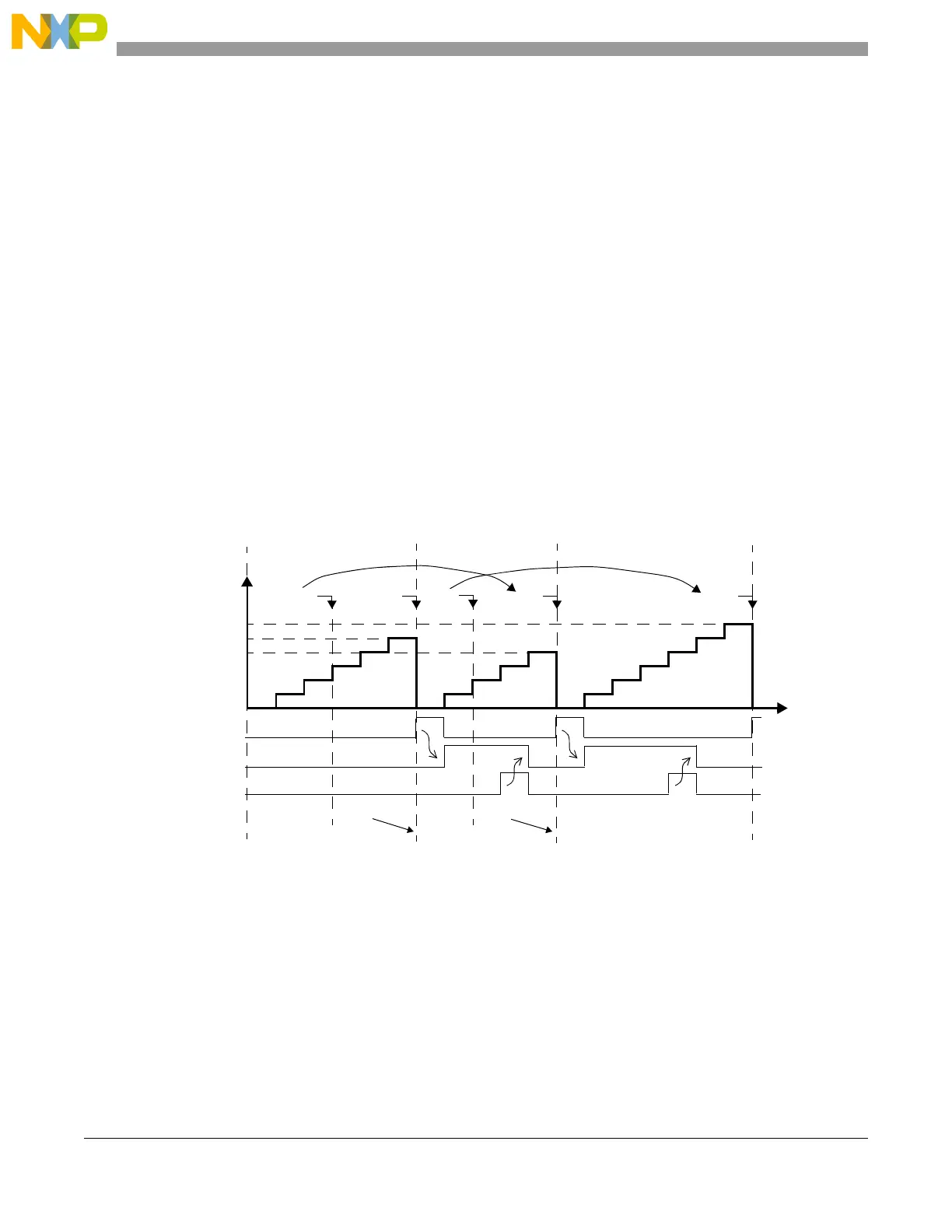
Figure 24-32 describes the counter cycle for several A1 values. Register A1 is loaded with A2 register
value at the cycle boundary. Thus any value written to A2 register within cycle n will be updated to A1 at
the next cycle boundary and therefore will be used on cycle n+1. The cycle boundary between cycle n and
cycle n+1 is defined as when the internal counter transitions from A1 value in cycle n to 0x1 in cycle n+1.
Note that the FLAG is generated at the cycle boundary and has a synchronous operation, meaning that it
is asserted one system clock cycle after the FLAG set event.
Figure 24-32. Modulus Counter Buffered (MCB) Up Count mode
Figure 24-33 describes the MCB in up/down counter mode (MODE[0:6] = 10101bb). A1 register is
updated at the cycle boundary. If A2 is written in cycle n, this new value will be used in cycle n+1 for A1
match. Flags are generated only at A1 match start if MODE[5] is 0. If MODE[5] is set to 1 flags are also
generated at the cycle boundary.
EMIOSCNT[n]
TIME
write to A2 match A1 match A1 match A1
write to A2
0x000001
0x000005
0x000006
0x000007
FLAG set event
A1 value
0x000006
0x000005
0x000007
0x000007
0x000005 0x000007
A2 value
FLAG pin/register
Prescaler ratio = 1
cycle n
cycle n+1 cycle n+2
FLAG clear
 Loading...