MPC5604B/C Microcontroller Reference Manual, Rev. 8
Freescale Semiconductor 571
Figure 24-45. OPWMB mode with 0% duty cycle
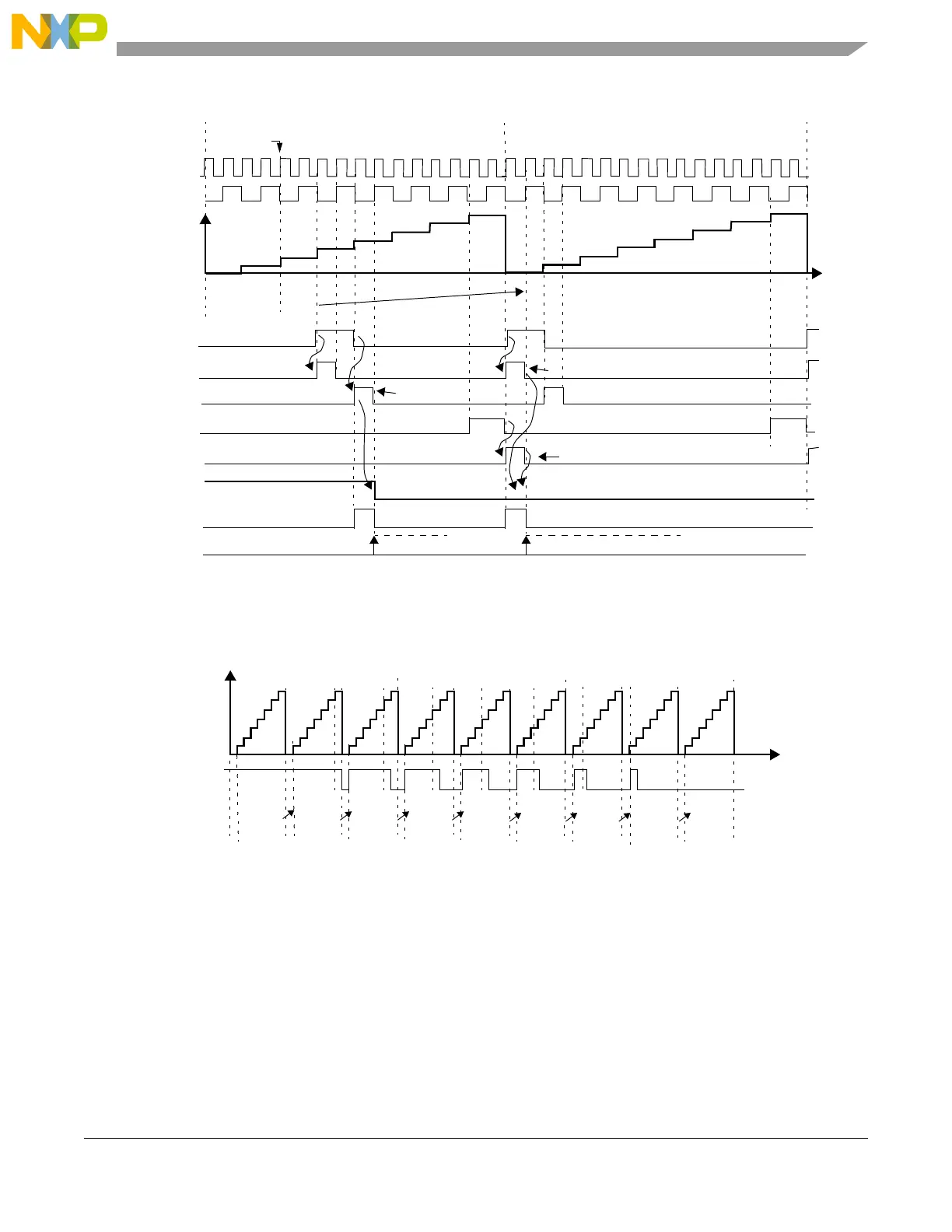
Figure 24-46 shows a waveform changing from 100% to 0% duty cycle. EDPOL in this case is zero. In
this example B1 is programmed to the same value as the period of the external selected time base.
Figure 24-46. OPWMB mode from 100% to 0% duty cycle
In Figure 24-46 if B1 is set to a value lower than 0x8 it is not possible to achieve 0% duty cycle by only
changing A1 register value. Since B1 matches have precedence over A1 matches the output pin transitions
to the opposite of EDPOL bit at B1 match. Note also that if B1 is set to 0x9, for instance, B1 match does
not occur, thus a 0% duty cycle signal is generated.
1
4
match A1 negedge detection
8
A1 value
0x000004
A1 match
A1 match negedge detection
output pin
EDPOL = 0
Selected
TIME
match B1 negedge detection
B1 match
B1 match negedge detection
B1 value
0x000008
clock
prescaler
A2 value
0x000000
write to A2
0x000000
A1 match posedge detection
match A1 posedge detection
1
cycle n
cycle n+1
8
counter bus
FLAG set event
FLAG pin/register
0x000008
0x000007 0x000006 0x000005
0x000004
0x000003 0x000002
0x000001
0x000000
0%
100%
Selected
EDPOL = 0
A1 value
B1 value
Output pin
0x000008
Prescaler = 1
cycle 1 cycle 2 cycle 3 cycle 4 cycle 5 cycle 6 cycle 7 cycle 8 cycle 9
counter bus
0x000007
0x000006 0x000005 0x000004
0x000003
0x000002 0x000001
0x000000
A2 value