MPC5604B/C Microcontroller Reference Manual, Rev. 8
748 Freescale Semiconductor
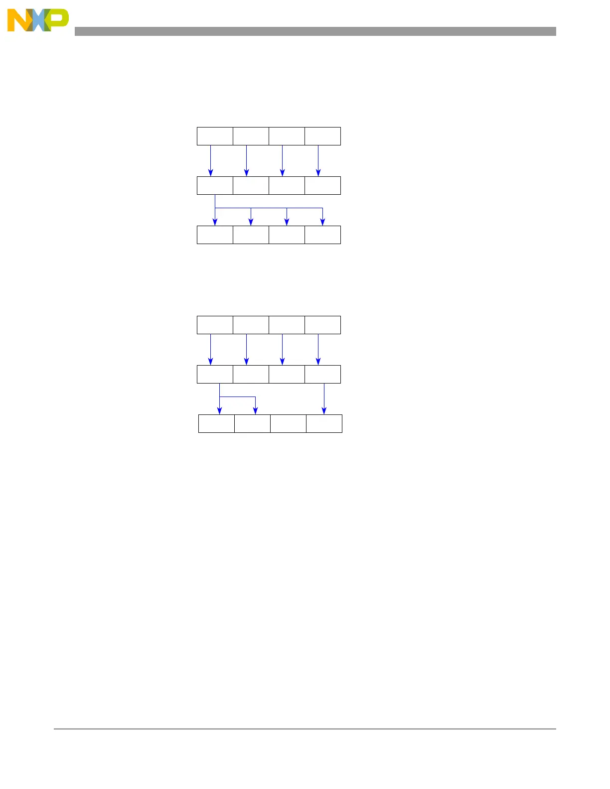
In Figure 29-7 a 32-bit wise protected register is shown. When SLBRn.WE[0] is set the data written to
SLBRn.SLB[0] is automatically written to SLBRn.SLB[3:1] also. Otherwise SLBRn.SLB[3:0] remains
unchanged.
Figure 29-7. Change Lock Settings for 32-bit Protected Addresses
In Figure 29-8 an example is shown which has a mixed protection size configuration:
Figure 29-8. Change Lock Settings for Mixed Protection
The data written to SLBRn.SLB[0] is mirrored to SLBRn.SLB[1] as the corresponding register is 16-bit
protected. The data written to SLBRn.SLB[2] is blocked as the corresponding register is unprotected. The
data written to SLBRn.SLB[3] is written to SLBRn.SLB[3].
29.6.2.2 Enable locking via mirror module space (area #3)
It is possible to enable locking for a register after writing to it. To do so the mirrored module address space
must be used. Figure 29-9 shows one example:
1
SLB0 SLB1 SLB2 SLB3
SLBRn.WE[3:0]
SLBR.SLB[3:0]
update lock bits
to SLB0
write data
to SLB1 to SLB2 to SLB3
XXX
SLB0 SLB1 0 SLB3
SLBR
update lock bits
1SLBRn.WE[3:0]
to SLB0
write data
to SLB1 to SLB2 to SLB3
XX1