Remote Output setup 5 Connectivity settings
4. For Remote Output Type, choose the type:
a.
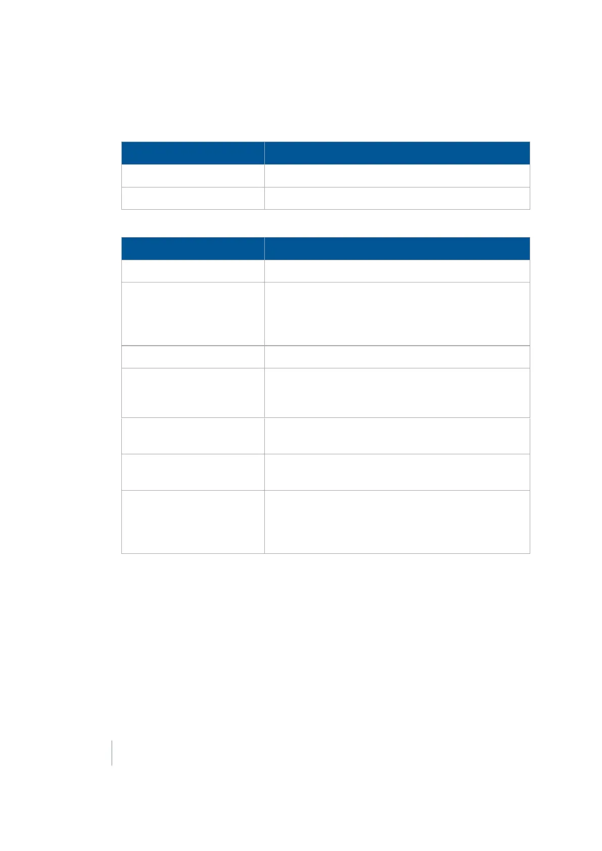
For Time Based Pulse, enter:
Setting Explanation
Time The pulse interval in seconds
Duration The pulse duration in milliseconds
b.
For Distance Based Pulse, enter:
Setting Explanation
Lead Time See
Calibrate implement lead time (page 133)
.
Distance The distance in meters/decimal feet/feet and inches. The
pulse occurs at each increment of this distance. The first
pulse occurs at the A point. Pulse remote output is not
recommended for Headland patterns.
Duration The duration of the pulse in milliseconds (ms)
Within Line Distance The pulse occurs only when the vehicle is within this
distance of being online. If the vehicle is more than this
distance offline, no pulse occurs
Design Trigger Color The color of the pulse indicator that will display on the
screen when the system automatically outputs a pulse
Manual Trigger Color The color of the pulse indicator that will display on the
screen when you press the manual trigger button
Trigger Limits If you select
None
, the pulses triggered by the system are
unlimited. If you select
Edit
, enter the maximum number
of pulses (per swath) that will be triggered after you pass
the A point.
Note – This option works with straight AB and A+ lines.
For using remote output using distance based pulses, see Distance-based pulse operation
(page 415).
c.
For When Within Area Feature, enter the Lead Time. Calibrate the Lead Time setting to match
your implement. See Calibrate implement lead time (page 133). The pulse occurs only
when Remote Output is enabled. You must also enable Remote Output for each area
feature individually in the Mapping setup. See Field feature use (page 356).
d. For When Engaged, there are no options to set. Remote output occurs when the system is
engaged.
132 FM-1000 Integrated Display User Guide Version 9.25, Revision B