5 Connectivity settings Remote Output setup
e.
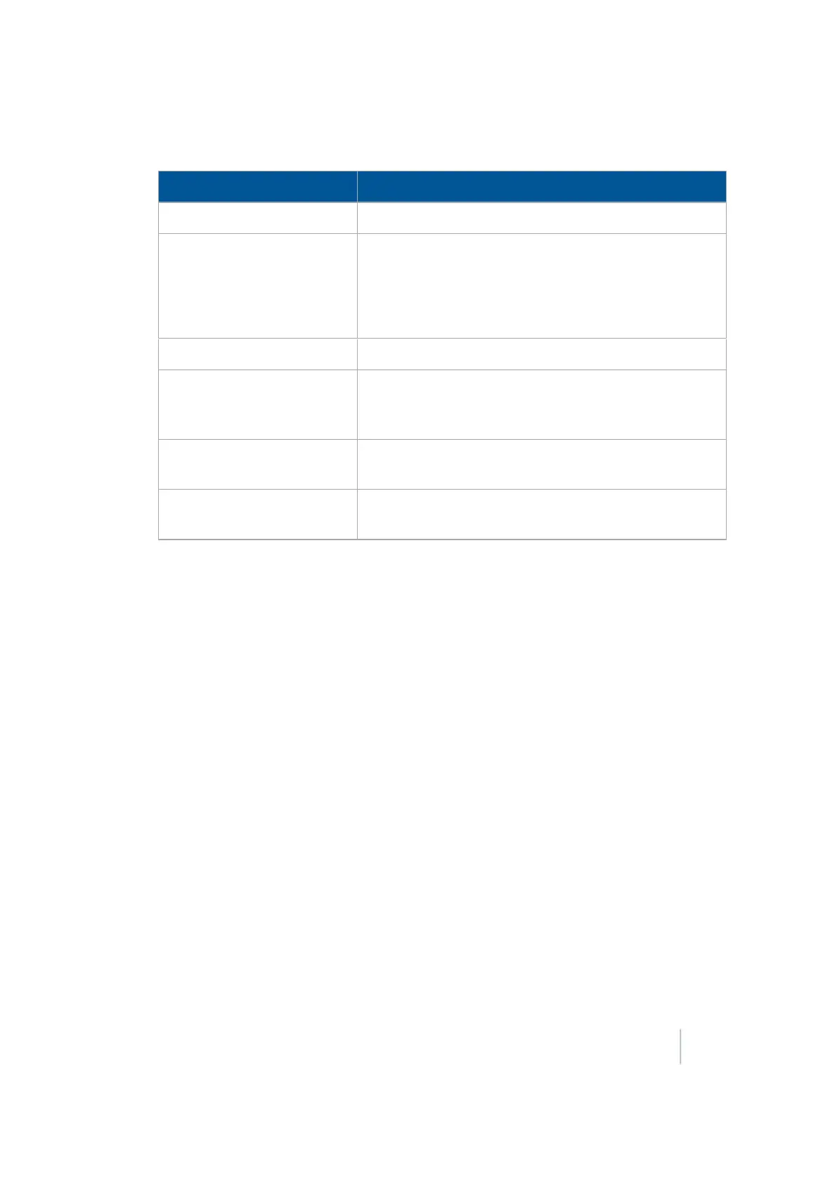
For When Crossing a Line Feature, enter:
Setting Explanation
Lead Time See
Calibrate implement lead time (page 133)
.
Distance
The distance in meters/decimal feet/feet and inches. The
pulse occurs at each increment of this distance. The first
pulse occurs at the A point.
Note –
Pulse remote output is not recommended for
Headland patterns.
Duration The duration of the pulse in milliseconds (ms)
Within Line Distance The pulse occurs only when the vehicle is within this
distance of being online. If the vehicle is more than this
distance offline, no pulse occurs
Design Trigger Color The color of the pulse indicator that will display on the
screen when the system automatically outputs a pulse
Manual Trigger Color The color of the pulse indicator that will display on the
screen when you press the manual trigger button
Be sure to edit the line feature to enable remote output and the trigger warning. See Line
feature settings (page 147). Complete the settings and tap OK.
Note – This option works with straight AB and A+ lines, pivots and curves.
For using remote output using when crossing a line feature, see Crossing a line feature
operation (page 416).
5.
Tap OK when your are finished.
Calibrate implement lead time
There is usually a gap between the time when the system generates a pulse and the time when that
pulse triggers an action on the implement. To compensate for this system delay, you can set a lead
time to trigger the pulse slightly early so that the action occurs at the correct location.
For this calibration, drive the vehicle along a line and back, using Remote Output to mark points on
the ground. If the remote output is correctly calibrated, the points that you create when driving in
both directions will be close together.
To calibrate implement lead time:
1. Set front/back offset (page 134).
2. Calibrate front/back offset (page 134).
3. Set lead time (page 134).
Version 9.25, Revision B FM-1000 Integrated Display User Guide 133