April 2017
8-5
Xerox® VersaLink® B7025/B7030/B7035 Multifunction Printer
Product Technical Overview
Launch Issue
Main Power
NOTE: A video is available on the EDOC that provides additional information. The video is
accessible from the Library menu on the Service Interface.
AC Power
The Xerox® VersaLink® B7025/B7030/B7035 machines are equipped a power button on the
UI and a main power switch on the front of the IOT. To access the main power switch, open the
front cover assembly.
Refer to GP 10 for power off, quick restart and power on procedures.
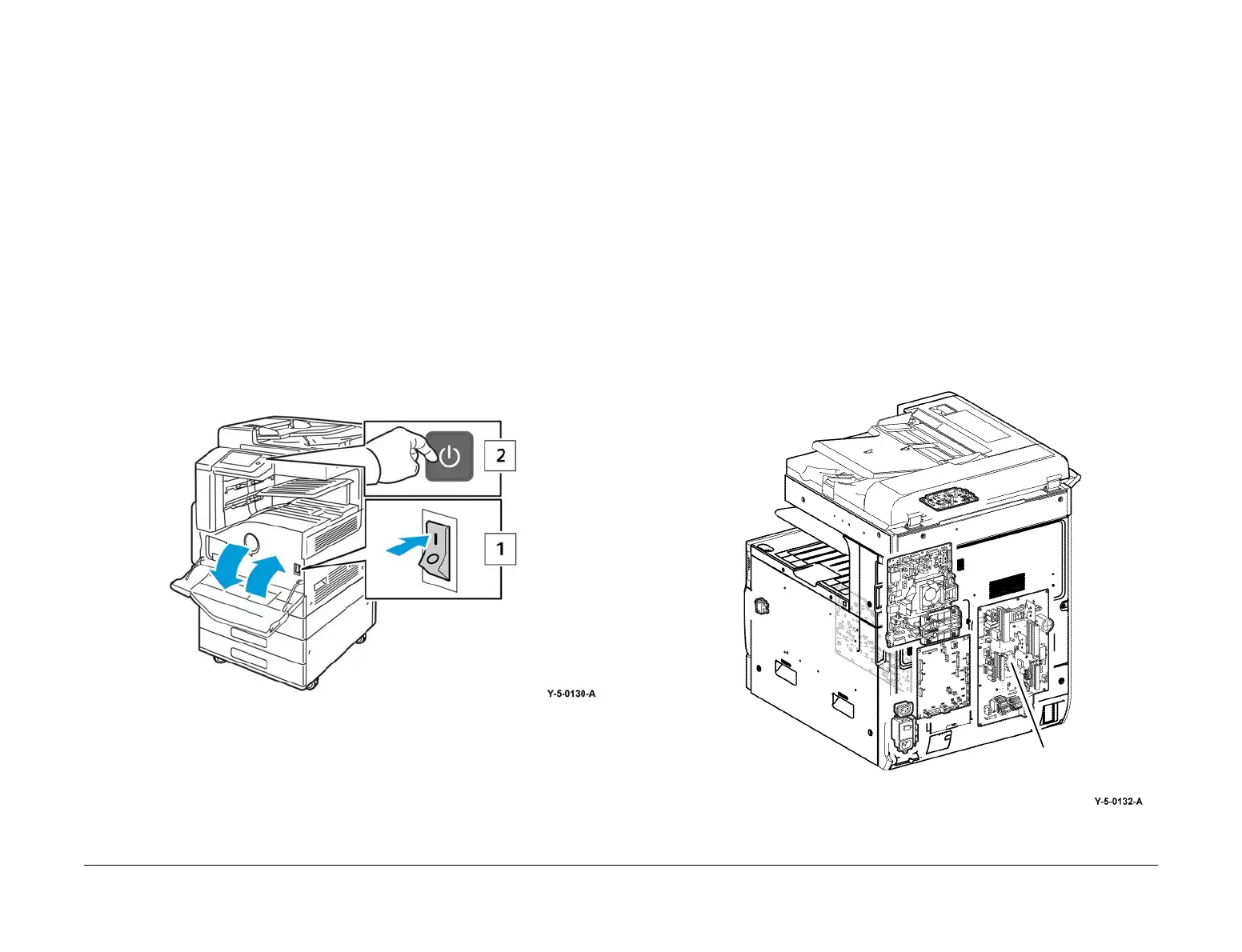
Closing the main power switch supplies AC power to the low voltage power supply, from which
it is distributed throughout the machine, Figure 1, item 1. The AC power is converted into
+5VDC standby power which is supplied to the ESS PWB (and Fax if installed). The ESS PWB
supplies 5VDC power to the UI power button, Figure 1, item 2.
With only the main power switch on there is no generation of either +5V power or +24V power.
This cannot occur until the power button on the UI is pressed.
The ESS PWB monitors the UI power button. When the UI power button is pressed the ESS
PWB detects the change in status and enables the low voltage power supply to begin produc
-
ing and distributing both the +5VDC and +24VDC power required for operation.
Refer to Chain 1 BSDs.
Figure 1 Main power switch and UI power button
The main functions of the AC power are as follows:
• Provides ground fault interrupt and filtered power.
• Supplies AC power to the main power switch.
• Supplies AC power via the main power switch to the low voltage power supply for distribu-
tion to the finisher and PWS outlets.
• Supplies AC power to the low voltage power supply for conversion into standby +5VDC,
+5VDC, and +24VDC power.
Low Voltage DC Power
With only the main power switch on, power on ACH is supplied to the +5VDC and +24VDC
power generation circuits on the LVPS, Figure 2. However, these circuits will not begin gener
-
ating low voltage power until the power switch also is turned on and they receive the required
on signals from the ESS PWB.
Also with only the main power switch on, STBY +5VDC power is routed to the ESS PWB so
that it can produce the +3.3VDC and +3VDC power required to monitor system status.
After the power switch is turned on, the +5VDC on/off signal, the +24VDC on/off signal, and the
+5VDC C-F On/off signal (fax) cause the low voltage power generation circuits to begin opera
-
tion.
AC power is also routed via the LVPS to the finisher and accessory outlets.
Refer to:
• BSD 1.3 LVPS Control
• BSD 1.4 DC Power Generation (1 of 2)
• BSD 1.5 DC Power Generation (2 of 2)
Figure 2 LVPS PWB
LVPS PWB
 Loading...