April 2017
4-123
Xerox® VersaLink® B7025/B7030/B7035 Multifunction Printer
REP 13.28, REP 13.29
Repairs and Adjustments
Launch Issue
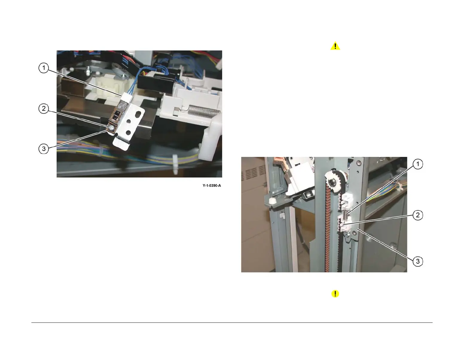
4. Remove the compiler no paper sensor, Figure 2:
a. Disconnect the connector (1).
b. Remove the screw (2).
c. Remove the compiler tray no paper sensor (3).
Figure 2 Compiler tray no paper sensor removal
Replacement
The replacement is the reverse of the removal procedure.
REP 13.29 Front/Rear Carriage Assembly
Parts List on PL 13.15
Removal
WARNING
Switch off the electricity to the machine. Refer to GP 10. Disconnect the power cord
from the customer supply while performing tasks that do not need electricity. Electricity
can cause death or injury. Moving parts can cause injury.
1. Enter dC330, code 12-060 stacker motor up, to fully raise the stacker tray.
2. Remove the finisher front cover,REP 13.6.
3. Remove the rear upper cover, REP 13.7.
4. Remove the rear lower cover, REP 13.8.
5. Remove the stacker tray, REP 13.20.
6. Removing the carriage assembly, Figure 1:
a. Disconnect, then remove the spring (1).
b. Use a flat bladed screwdriver to release the belt clamp latch (2).aside and
c. Remove the stacker belt and carriage assembly.
NOTE: . The carriage bearings (2 each assembly) are not fastened to the shafts.
Ensure the bearings are retained when the carriage assembly is removed.
Figure 1 Carriage assembly removal
Replacement
CAUTION
Ensure that the front and rear carriage assemblies are installed at the same height.
The replacement is the reverse of the removal procedure.
 Loading...