April 2017
4-150
Xerox® VersaLink® B7025/B7030/B7035 Multifunction Printer
REP 60.4, REP 60.5
Launch Issue
Repairs and Adjustments
Replacement
1. The replacement is the reverse of the removal procedure.
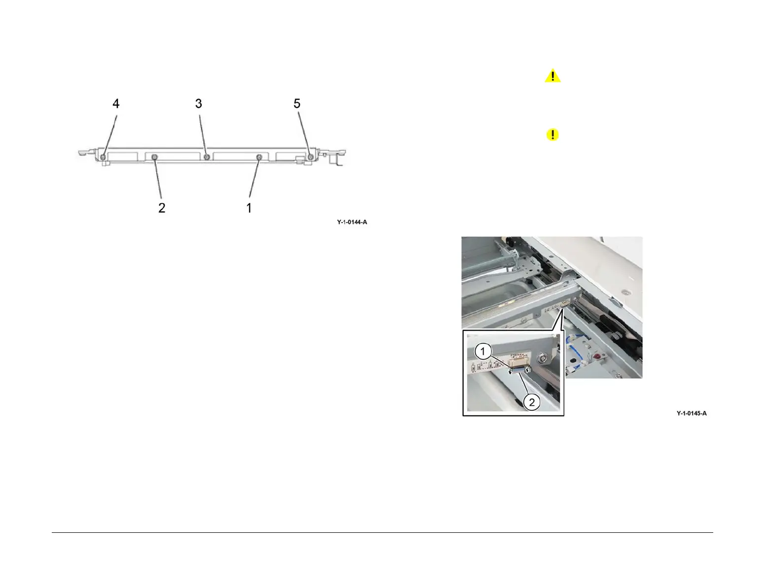
2. When installing the lamp assembly, first tighten screw (1), then screw (2), Figure 4.
3. When installing the LED bracket, first tighten screw (3), then screw (4), then screw (5),
Figure 4.
Figure 4 Screws
4. If a new lamp assembly is installed, enter dC135 HFSI Counter. Reset the HFSI counters
that follow:
• Chain-Link: 956-803
• Chain-Link: 956-804
REP 60.5 FFC LED Cable Assembly
Parts List on PL 60.20
Removal
WARNING
Switch off the electricity to the machine. Refer to GP 10. Disconnect the power cord
from the customer supply while performing tasks that do not need electricity. Electricity
can cause death or injury. Moving parts can cause injury.
CAUTION
Do not touch the chip on the lamp assembly.
1. Remove the DADF, REP 5.1.
2. Remove the upper rear cover, REP 28.5.
3. Disconnect the FFC LED cable assembly, Figure 1:
a. Move the connector housing catch (2) in the direction of the arrows.
b. Disconnect the FFC LED cable assembly (1).
Figure 1 FFC LED cable assembly
 Loading...