April 2017
8-91
Xerox® VersaLink® B7025/B7030/B7035 Multifunction Printer
Product Technical Overview
Launch Issue
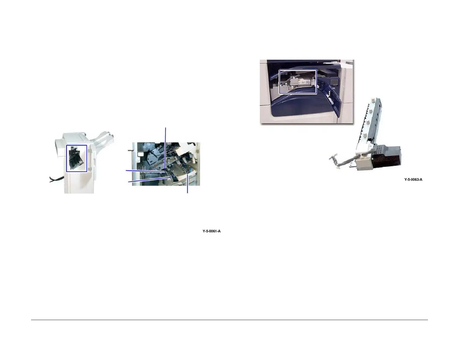
Stapler Mount Position
The position of the stapler mount is controlled by the stapler move position sensor.
As the stapler mount moves along the base frame, the light emitted between the two prongs of
the stapler move position sensor is interrupted by one of three positional tabs.
These are the end, front, and rear positional tabs.
The end positional tab is used to indicate the correct position along the base frame for single
stapling.
The front and rear positional tabs are used to indicate the correct position along the base frame
for double stapling. Refer to Figure 43.
Figure 43 Stapler mount position
Stapler Cartridge
The staple units contain a staple cartridge CRU, staple clinch motor, cam and a staple drive
mechanism.
When required, the staple clinch motor is energized to drive the cam.
One full rotation of the cam causes the staple drive mechanism to drive and clinch a staple,
stored in the staple cartridge CRU, through the paper set. Refer to PL 13.20.
Hole Punch Assembly
The hole punch assembly punches either 2 or 4 holes in Europe or 2 or 3 holes in North Amer-
ica. The hole punch assembly is installed within the horizontal transport. It is controlled by the
finisher PWB. Refer to Figure 44.
Figure 44 Hole punch assembly
Stapler move position
sensor
Front positional
tab
Rear positional
tab
End positional
tab
 Loading...