April 2017
4-111
Xerox® VersaLink® B7025/B7030/B7035 Multifunction Printer
REP 13.17
Repairs and Adjustments
Launch Issue
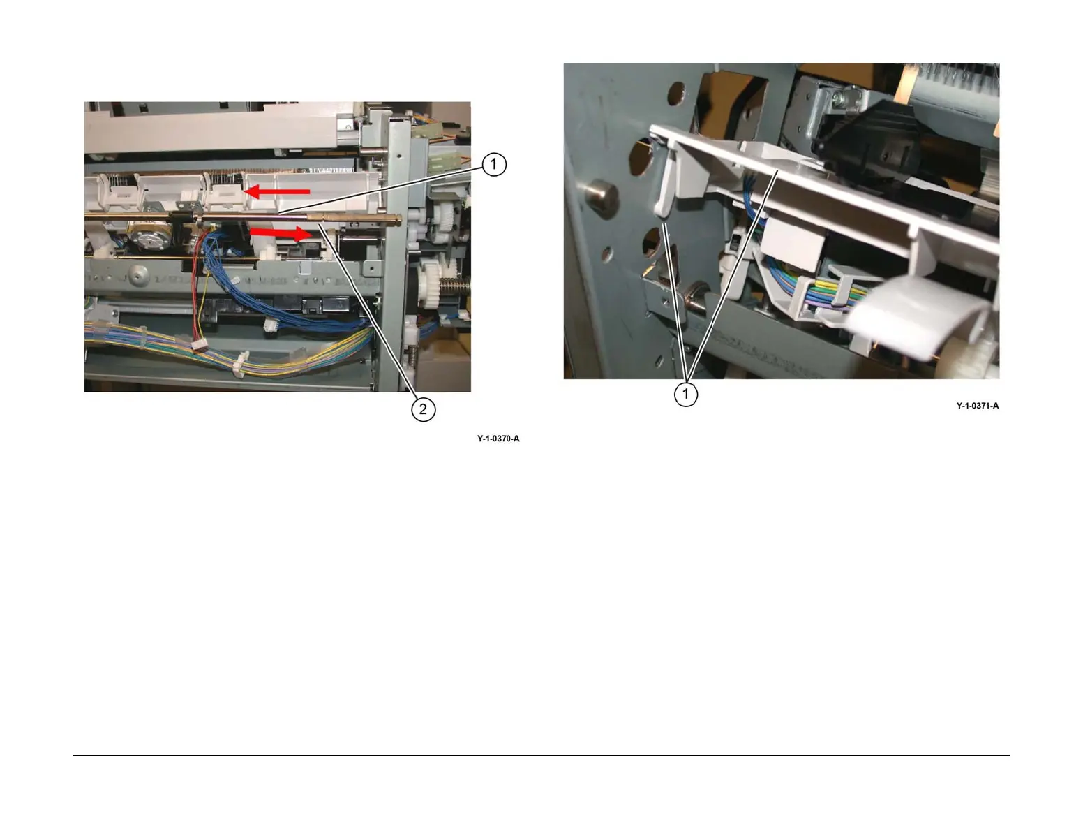
16. Remove the set clamp shaft, Figure 9:
a. Slide the shaft toward the front (1).
b. Slide the shaft toward the rear, then remove (2).
Figure 9 Set clamp shaft removal
17. Remove the compiler tray assembly (1), Figure 10.
Figure 10 Compiler tray assembly removal
18. Usually this level of compiler tray assembly removal is to facilitate removal of the front or
rear tamper motors, tamper home sensors or compiler tray no paper sensor. However, if
the compiler tray assembly is to be completely removed, it will be necessary to disconnect
all the connectors to the tamper motors, tamper home sensors and no paper sensor and
release the harnesses from the guides.
 Loading...