April 2017
4-172
Xerox® VersaLink® B7025/B7030/B7035 Multifunction Printer
REP 70.9
Launch Issue
Repairs and Adjustments
CAUTION
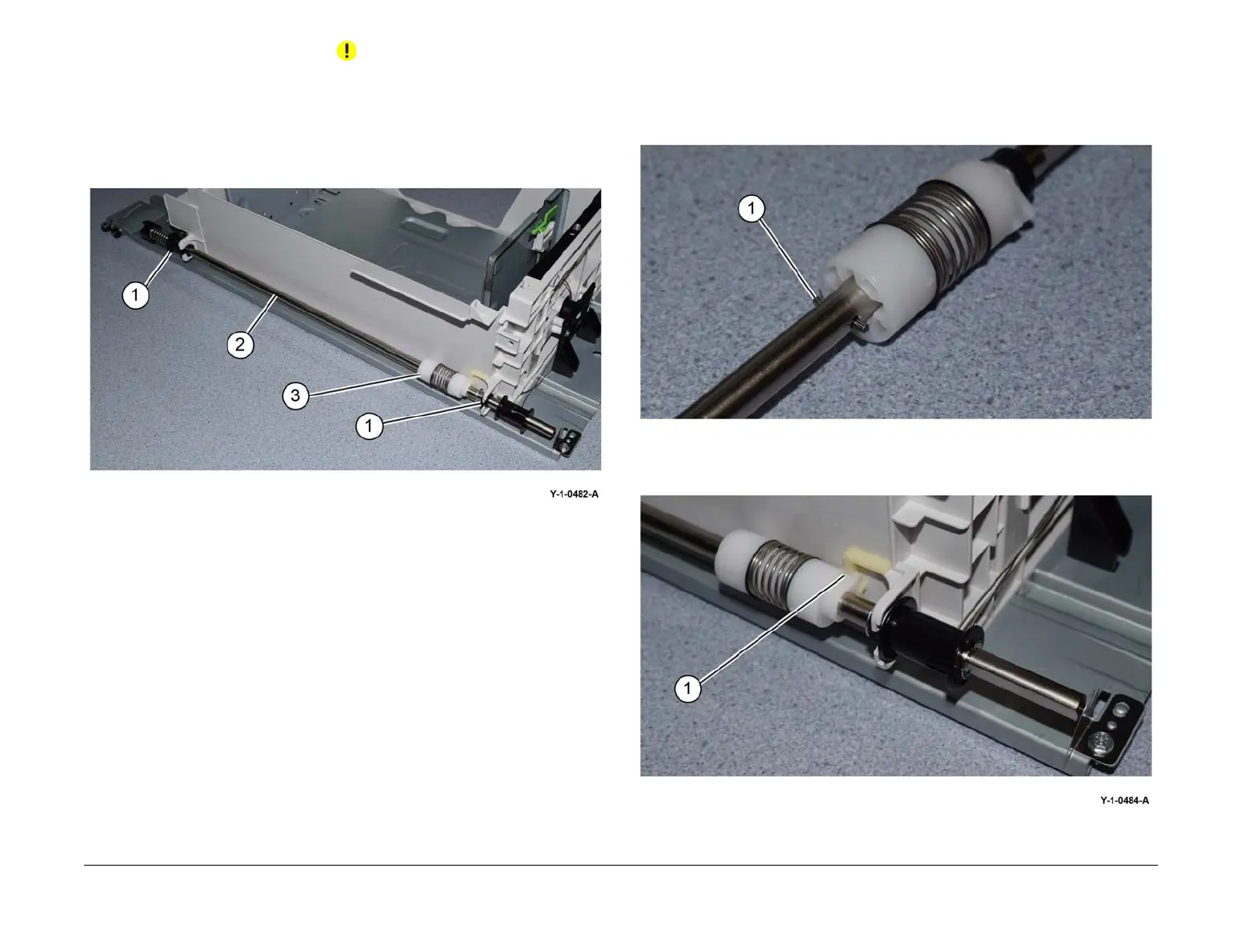
The lift shaft brake, item 3 in Figure 4, is secured on the lift shaft by a pin. Do not lose the pin
when the lift shaft is removed.
7. Remove the lift shaft, Figure 4:
a. Release the front and rear bearings (1).
b. Remove the lift shaft (2).
Figure 4 Lift shaft removal
8. If necessary, remove the front pulley bearing, E-clip and brake.
Replacement
1. The replacement is the reverse of the removal procedure.
NOTE: The thick E-clips secure the bearings, the thinner E-clips secure the pulleys.
2. Ensure the brake securing pin (1) is installed correctly, Figure 5.
Figure 5 Pin
3. Ensure the brake (1) is correctly positioned against the tray frame, Figure 6.
Figure 6 Brake
 Loading...