Home
Delta
Controller
ASDA-A2
Delta ASDA-A2 User Manual
4
of 1
of 1 rating
721 pages
Give review
Manual
Specs
To Next Page
To Next Page
To Previous Page
To Previous Page
Loading...
Chapter 4 Panel Displa
y
and Operation
ASD
A-A2
Revision February, 2017
4-9
4.4 General
Function
4.4.1 Operation of Fa
ult Record Display
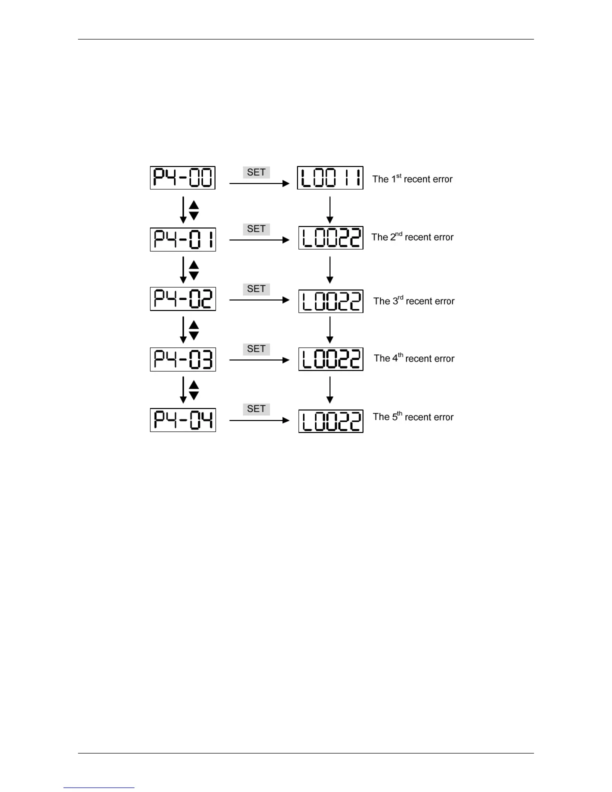
When it is in Parameter Mode, select P4-00~P4-04 and press the SET Key, the corresponding
fault record will be shown
.
129
131
Table of Contents
Default Chapter
2
Revision February
2
Safety Precautions
3
The Symbol of Danger, Warning and Stop
3
Safe Maintenance and Inspection
4
Safe Operation
4
Main Circuit Wiring
5
Terminal Wiring of the Main Circuit
5
Table of Contents
6
About this Manual
15
A Complete and Workable Servo Set Should Include...
16
Inspection
16
Inspection and Model Explanation
16
Chapter 1 Inspection and Model Explanation
17
Servo Drive Power Input
17
Product Model
18
Nameplate Information
18
Model Explanation
19
Model Type
19
220V Series
21
Servo Drive and Corresponding Servo Motor
21
400V Series
23
220V Series - Front View
24
Each Part of the Servo Drive
24
220V Series - Top View
25
220V Series - Bottom View
26
400V Series - Front View
27
400V Series - Top View
28
400V Series - Bottom View
29
Ambient Conditions of Installation
30
Ambient Conditions of Storage
30
Chapter 2 Installation
30
Notes
30
Installation Direction and Space
31
Scheme of Installation
32
Specification of Circuit Breaker and Fuse
34
EMI Filter Selection
35
EMI Filter Installation
36
General Precaution
36
Motor Cable Selection and Installation Precautions
37
Selection of Regenerative Resistor
38
Specification of Built-In Regenerative Resistor Provided by ASDA-A2 220V Series
38
Specification of Built-In Regenerative Resistor Provided by ASDA-A2 400V Series
38
Regenerative Power Selection
40
Calculation Procedure
42
Simple Selection
44
Allowable Frequency When the Servo Motor Runs Without Load (Times/Min)And Uses a Built-In Regenerative Resistor
44
Allowable Frequency of Regenerative Resistor When the Servo Drive Runs Without Load (Times/Min)
44
Dimensions of Regenerative Resistor
46
Connections - 220V Series
48
Connecting to Peripheral Devices
48
Chapter 3 Wiring
48
Connectors and Terminals of Servo Drive
49
Wiring Method
51
Wiring Method of Three-Phase Power Supply (Suitable for All Series)
52
Specification of Motor Power Cable
53
Specification of Encoder Cable Connector
55
Specification and Definition of Encoder Connector
56
Encoder Connection (Diagram 2)
57
Selection of Wiring Rod
59
Connections - 400V Series
61
Connecting to Peripheral Devices (400V)
61
Connectors and Terminals of the Servo Drive
63
Wiring Method (400V)
65
Specification of Motor Power Cable (400V)
66
Specification of Encoder Connector
68
Encoder Connection (Diagram 2) (400V)
69
Selection of Wiring Rod (400V)
70
200W (Included) or Models below (Without Built-In Regenerative Resistor)
72
Basic Wiring - 220V Series
72
400W ~ 4.5 Kw Models (with Built-In Regenerative Resistor)
73
5.5Kw to 15Kw Models (with Built-In Fan but no Regenerative Resistor)
74
750W to 1.5Kw Models (with Built-In Regenerative Resistor and Fan)
75
Basic Wiring - 400V Series
75
2Kw to 7.5Kw Models (with Built-In Fan but no Regenerative Resistor)
76
I/O Signal (CN1) Connector Terminal Layout
77
General Signals
79
Signals Explanation of Connector CN1
79
The Explanation of DO Signal Default Setting
80
The Explanation of DI Signal Default Setting
82
Default Value of DI Input Function
85
Default Value of DO Output Function
87
C1: Speed, Input of Torque Analog Command
89
C2: Analog Monitor Output MON1 ,MON2
89
Wiring Diagrams (CN1)
89
C3-1: the Source of Pulse Input Is Open-Collector NPN Equipment Which Applies the Internal Power of the Servo Drive
90
C3-2: the Source of Pulse Input Is Open-Collector PNP Equipment Which Applies the Internal Power of the Servo Drive
90
C3-3: the Source of Pulse Input Is Open-Collector NPN Equipment and Applies the External Power
91
C3-4: the Source of Pulse Input Is Open-Collector PNP Equipment and Applies the External Power
91
C4-1: Pulse Input (Line Driver)
92
C4-2: High-Speed Pulse Input (Line Driver)
92
C5: Wiring of DO Signal
93
C6: Wiring of DO Signal
93
C7: Wiring of DO Signal
94
C8: Wiring of DO Signal
94
C9 - C12 - the Wiring of DI
95
NPN Transistor, Common Emitter (E) Mode (SINK Mode)
95
PNP Transistor, Common Emitter (E) Mode (SOURCE Mode)
95
C13: Encoder Signal Output (Line Driver)
96
C14: Encoder Signal Output (Opto-Isolator)
96
C15: Encoder OCZ Output (Open-Collector Z Pulse Output)
96
Application: Using CN1 Quick Connector for Wiring
97
DI and DO Signal Specified by Users
97
Example of Wiring
99
Wiring and Installation of CN1 Quick Connector
100
CN2 Connector
101
The Definition of each Signal
102
About Shielding and Ground
102
Wiring of CN3 Connector
104
Layout of CN3 Connector
104
Connection between PC and Connector CN3
105
CN4 Serial Connector (USB)
106
CN5 Connector (Full-Closed Loop)
107
CN6 Connector (Canopen)
108
Extension Digital Input Connector of CN7
110
CN8 Connector of Battery Box
111
Standard Connection Example - 220V Series
112
Position (PT) Control Mode
112
Position (PR) Control Mode
113
Speed Control Mode
114
Torque Control Mode
115
Communication Mode
116
Standard Connection Example - 400V Series
117
Position (PT) Control Mode Chart
117
Position (PR) Control Mode Chart
118
Speed Control Mode Chart
119
Torque Control Mode Chart
120
Communication Mode Chart
121
Panel Description
122
Chapter 4 Panel Display and Operation
122
Parameter Setting Procedure
123
Parameter Mode
124
Edit Setting Mode
125
Status Display
126
Save Setting Display
126
Decimal Point, Alarm Message
126
Positive and Negative Sign Setting
126
Monitor Display
127
General Function
130
Operation of Fault Record Display
130
JOG Mode
131
Force DO Output
132
Digital Input Diagnosis Operation
133
Digital Output Diagnosis Operation
133
Inspection Without Load
134
Chapter 5 Trial Operation and Tuning
134
Applying Power to the Servo Drive
135
JOG Trial Run Without Load
139
Trial Run Without Load (Speed Mode)
140
The Speed Command Selection Table
141
Register Parameter
141
Trial Run Without Load (Position Mode)
142
Tuning Procedure
144
Flowchart of Tuning Procedure
145
Inertia Estimation Flowchart (with Mechanism)
146
Flowchart of Auto Tuning
147
Flowchart of Semi-Auto Tuning
148
Limit of Inertia Ratio
149
Mechanical Resonance Suppression Method
151
Tuning Mode and Parameters
152
Tuning in Manual Mode
153
Position Control Gain (KPP, Parameter P2-00)
153
Speed Control Gain (KVP, Parameter P2-04)
153
Speed Integral Compensation (KVI, Parameter P2-06)
153
Anti-Interference Gain (DST, Parameter P2-26)
154
Low-Pass Filter of Resonance Suppression (NLP, Parameter P2-25)
154
Position Feed Forward Gain (PFG, Parameter P2-02)
154
Selection of Operation Mode
156
Chapter 6 Control Mode of Operation
156
Position Mode
158
Position Command in PT Mode
158
Filter Width
159
Logic Type
160
The Source of External Pulse
161
Position Command in PR Mode
162
Control Structure of Position Mode
163
S-Curve Filter (Position)
164
Pulse Command Inhibit Input Function (INHP)
164
Electronic Gear Ratio
167
Low-Pass Filter
170
Timing Diagram in Position Mode (PR)
171
Gain Adjustment of Position Loop
172
Low-Frequency Vibration Suppression in Position Mode
174
Speed Mode
179
Selection of Speed Mode
179
Control Structure of Speed Mode
180
Smooth Speed Command
181
S-Curve Filter
181
TACC Acceleration Constant of S-Curve
181
TDEC Deceleration Constant of S-Curve
182
Acceleration / Deceleration Constant of S-Curve
183
Analog Speed Command Filter
183
Command End Low-Pass Filter
184
The Scaling of Analog Command
185
VCM Maximum Speed of Analog Speed Command
185
Timing Diagram in Speed Mode
186
Gain Adjustment of Speed Loop
186
Aut2Tuning Mode Selection
187
KVI Speed Integral Compensation
188
KVP Speed Loop Gain
188
Manual Mode
188
KVF Speed Feed Forward Gain
189
Frequency Domain
190
Time Domain
191
Auto Mode
192
Resonance Suppression
193
DPH1 Resonance Suppression (Notch Filter) Attenuation Rate (1)
193
NCF1 Resonance Suppression (Notch Filter) (1)
193
DPH2 Resonance Suppression (Notch Filter) Attenuation Rate (2)
194
DPH3 Resonance Suppression (Notch Filter) Attenuation Rate (3)
194
NCF2 Resonance Suppression (Notch Filter) (2)
194
NLP Low-Pass Filter of Resonance Suppression
195
Settings of P2-47
196
Flowchart of Auto Resonance Suppression
197
The Effect Via Low-Pass Filter (Parameter P2-25) Diagram
198
Resonance Suppression with Low-Pass Filter
199
Torque Mode
200
Selection of Torque Command
200
Control Structure of Torque Mode
201
Smooth Torque Command
202
The Scaling of Analog Command
202
Timing Diagram in Torque Mode
203
Dual Mode
204
Speed / Position Dual Mode
205
Speed / Torque Dual Mode
205
Torque / Position Dual Mode
206
Others
207
The Use of Speed Limit
207
The Use of Torque Limit
207
Analog Monitor
208
AOUT Polarity Setting of Encoder Pulse Output
209
MON1 Analog Monitor Output Proportion
210
MON2 Analog Monitor Output Proportion
210
DOF1 Offset Adjustment Value of Analog Monitor Output (Ch1)
211
DOF2 Offset Adjustment Value of Analog Monitor Output (Ch2)
211
The Use of Brake
212
Timing Diagram of Brake Control
212
The Wiring Diagram of Using Mechanical Brake
213
Timing Diagram of Control Power and Main Power
213
Motion Control Functions of ASDA-A2
214
System Information
214
Chapter 7 Motion Control
214
Description of Monitoring Variables
215
The Descriptions of Monitoring Variables Attribute
215
Explanation of Monitoring Variables
216
Description of Data Array
221
Content of Communication Command: Write into Data Array
223
Content of Communication Command: Set the Reading Address of Data Array
223
Content of Communication Command: Read Data Array
223
Description of Motion Axes
224
Description of PR Mode
225
The Difference between General PR Mode and the One in ASDA-A2
225
The Position Unit of PR Mode
226
Description of Register in PR Mode
226
Homing Description of PR Mode
228
DI/DO Provided by PR Mode and Diagrams
229
Parameter Settings
231
Destination: Setting of the Written Target
234
SOURCE: Settings of Data Source
235
Special Function: TYPE = 0Xa, Indexing Command
235
Homing Definition: P6-00 ~ P6-01, (64 Bits) One Set of PR
237
The Priority of Interrupt Command Is Higher than Overlap (Table)
238
The Relation between the Previous Path and the Next Path
238
Programming the Path in PR Mode
239
The Description of E-Cam Function
240
The Main Feature of E-Cam Is as the Followings...
241
Clutch, the Description Is as Follows
242
E-Cam Provided by this Servo Drive and below Is Its Functional Diagram
242
Master Axis, the Description Is as Follows
242
Cam, the Description
245
Gear #1, the Description
245
CAPTURE Features Table
247
Digital Output of E-Cam, the Description
247
Function Description of CAPTURE (Data Capture)
247
Compare Features Table
249
Function Description of COMPARE (Data Compare)
249
The Diagram of CAP
249
The Diagram of COMPARE
250
Parameter Definition
252
Control Mode Description
252
Special Symbol Description
252
Chapter 8 Parameters
252
List of Parameters
253
Monitor and General Output Parameter
253
Filter and Resonance Suppression Parameter
255
Gain and Switch Parameter
256
Position Control Parameter
257
External Pulse Command (PT Mode)
257
Register Control Command (PR Mode)
257
Speed Control Parameter
258
Torque Control Parameter
259
Planning of Digital Input / Output Pin and Output Setting Parameter
260
Communication Parameter
261
Diagnosis Parameter
262
Parameter Description
264
P0-XX Monitor Parameters
264
ALE Alarm Code Display of Drive (Seven-Segment Display)
264
VER Firmware Version
264
Alarm of Servo Drive
265
Alarm of Canopen Communication
266
Alarm of Motion
267
STS Drive Status
268
MON Analog Output Monitor
269
CM1 Status Monitor Register 1
271
TSON Power on Time
271
CM2 Status Monitor Register 2
272
CM3 Status Monitor Register 3
272
CM4 Status Monitor Register 4
273
CM5 Status Monitor Register 5
273
CM1A Status Monitor Register 1 Selection
274
CM2A Status Monitor Register 2 Selection
274
CM3A Status Monitor Register 3 Selection
275
CM4A Status Monitor Register 4 Selection
275
CM5A Status Monitor Register 5 Selection
275
MAP1 Mapping Parameter # 1
276
MAP2 Mapping Parameter # 2
276
MAP3 Mapping Parameter # 3
277
MAP4 Mapping Parameter # 4
277
MAP5 Mapping Parameter # 5
278
MAP6 Mapping Parameter # 6
278
MAP7 Mapping Parameter # 7
278
MAP1A Target Setting of Mapping Parameter P0-25
279
MAP8 Mapping Parameter # 8
279
MAP2A Target Setting of Mapping Parameter P0-26
281
MAP3A Target Setting of Mapping Parameter P0-27
281
MAP4A Target Setting of Mapping Parameter P0-28
282
MAP5A Target Setting of Mapping Parameter P0-29
282
MAP6A Target Setting of Mapping Parameter P0-30
283
MAP7A Target Setting of Mapping Parameter P0-31
283
MAP8A Target Setting of Mapping Parameter P0-32
284
PCMN Status Monitor Register (for PC Software)
284
PCMNA Status Monitor Register Selection (for PC Software)
285
SVSTS Servo Digital Output Status Display
285
APSTS Absolute Coordinate System Status
286
UAP Renew Encoder Absolute Position
286
Aprencoder Absolute Position (Multiturn)
287
APP Encoder Absolute Position (Pulse Number Within Single Turn or PUU)
288
ZDRT General Range Compare Digital Output – Filtering Time
288
ZON1H General Range Compare Digital Output – Upper Limit of 1St Monitoring Variable
289
ZON1L General Range Compare Digital Output – Lower Limit of 1St Monitoring Variable
289
VGT the Time When Voltage Exceeding 400V
290
P1-XX Basic Parameters
291
PTT the Type of External Pulse Input
291
High-Speed and Low-Speed Pulse Input Chart
292
High-Speed Pulse Input Chart
293
Low-Speed Pulse Input Chart
293
CTL Input Setting of Control Mode and Control Command
294
Control Mode Settings
295
Multiple Mode
295
Settings
295
PSTL Speed and Torque Limit Setting
296
Torque Output Direction Settings
296
AOUT Polarity Setting of Encoder Pulse Output Chart
297
Polarity of Encoder Pulse Output
298
Polarity of Monitor Analog Output
298
SFLT Analog Speed Command (Low-Pass Filter)
299
TFLT Analog Torque Command (Low-Pass Filter)
299
PFLT Smooth Constant of Position Command (Low-Pass Filter)
300
SP1 Internal Speed Command 1/Internal Speed Limit 1
300
Example of Inputting Internal Speed Limit
301
Settings: Internal Speed Command 1: the Setting of the First Internal Speed Command
301
SP2 Internal Speed Command 2/Internal Speed Limit 2
301
SP3 Internal Speed Command 3/Internal Speed Limit 3
302
TQ1 Internal Torque Command 1/Internal Torque Limit 1
302
TQ2 Internal Torque Command 2/Internal Torque Limit 2
303
CXFT Capture Synchronous Axis – Threshold of Correction
304
TQ3 Internal Torque Command 3/Internal Torque Limit 3
304
CSOF Capture Synchronous Axis – Offset Compensation
305
YX: When Synchronous Axis Captures the Signal
305
TEET Compensation of Following Error-Additional Time Setting
306
CPCT Electronic Cam (E-Cam) Pulse Phase Compensation – Time Setting
307
CPEX CAPTURE / COMPARE – Additional Function Settings
307
CPMK CAPTURE – Masking Range Setting
308
Format: Hexadecimal
308
CPCL E-Cam Pulse Phase Compensation – Min. Frequency Setting of Master Axis
309
Format: Decimal
309
SPF1 PR Special Filter Settings
310
CMOF Compare-Offset Data of CMP (Can Reset to 0 Automatically)
312
CMOF Compare-Offset Data of CMP (Non-Volatile)
312
VSF1 Low-Frequency Vibration Suppression (1)
313
VSG1 Low-Frequency Vibration Suppression Gain (1)
313
VSF2 Low-Frequency Vibration Suppression (2)
314
VSG2 Low-Frequency Vibration Suppression Gain (2)
314
AVSM Auto Low-Frequency Vibration Supression Setting
315
VCL Low-Frequency Vibration Detection
315
LSTP Motor Stop Mode
316
P1-34 TACC Acceleration Constant of S-Curve
316
P1-35 TDEC Deceleration Constant of S-Curve
317
TSL Acceleration / Deceleration Constant of S-Curve
318
Version after V1.036 Sub00 Provides the Compensation Function of Following Error
318
GDR Inertia Ratio and Load Weight Ratio to Servo Motur
319
ZSPD Zero Speed Range Setting
319
SSPD Target Motor Detection Level
320
VCM Maximum Output of Analog Speed Command
320
MBT1 Enable Delay Time of Brake
321
TCM Maximum Output of Analog Torque Speed
321
GR1 Gear Ratio (Numerator) (N1)
322
MBT2 Disable Delay Time of Brake
322
GR2 Gear Ratio (Denominator) (M)
323
GR3 Pulse Number of Encoder Output
323
SPOK Speed Reached (DO:SP_OK) Range
324
MCOK Operation Selection of Motion Reached (DO.MC_OK)
325
Block Diagram
326
Description
326
SPOKWT Accumulative Time of Speed Reached
326
RES1 Regenerative Resistor Value
327
RES2 Regenerative Resistor Capacity
328
PER Position Completed Range
329
The Setting Value When Connecting Regenerative Resistor with Different Method
329
CRSHA Motor Crash Protection (Torque Percentage)
330
MSPD Maximum Speed Limit
330
OVW Output Overload Warning Level
330
CRSHT Motor Crash Protection Time
331
MFLT Analog Speed Command
331
FRCL Friction Compensation
332
PCCT Analog Position Command: Activation Control
333
Smooth Constant of Analog Position Command
334
PCM Max. Rotation Number of Analog Position Command
335
PFLT2 Position Command Moving Filter
335
FRES Resolution of Linear Scale for Full-Closed Loop Control
336
FCON Full-Closed Loop Control of Linear Scale
337
FERR Error Protection Range for Full-Closed Loop Control
337
FELP Low-Pass Filter Time Constant of Full-Closed Loop Control
338
AMSPD Maximum Rotation of Encoder Output Setting (OA, OB)
339
VCM2 Max. Speed of 2Nd Analog Speed Command
339
VCMLPF Abnormal Analog Input Voltage Level
340
VCMLPF Filter Switching Time between P1-40 and P1-81
340
HMTQL Torque Limit Setting
341
HMTQT Torque Limit Time Setting
341
P2-XX Extension Parameters
342
KPP Position Loop Gain
342
PPR Switching Rate of Position Loop Gain
342
PFF Smooth Constant of Position Feed Forward Gain
343
PFG Position Feed Forward Gain
343
P2-04 KVP Speed Loop Gain
344
SPR Switching Rate of Speed Loop Gain
344
P2-06 KVI Speed Integral Compensation
345
P2-07 KVF Speed Feed Forward Gain
345
DRT DI Debouncing Time
346
PCTL Special Parameter Write-In
346
DI1 Functional Planning
347
DI2 DI2 Functional Planning
347
DI3 DI3 Functional Planning
348
DI4 DI4 Functional Planning
348
DI5 DI5 Functional Planning
349
DI6 DI6 Functional Planning
349
DI7 DI7 Functional Planning
349
DI8 Functional Planning
350
DO1 Functional Planning
350
DO2 Functional Planning
351
DO3 Functional Planning
351
DO4 Functional Planning
352
DO5 Functional Planning
352
NCF1 Resonance Suppression (Notch Filter) (1)
352
P2-24 DPH1 Resonance Suppression (Notch Filter) Attenuation Rate (1)
353
P2-25 NLP Low-Pass Filter of Resonance Suppression
353
DST Anti-Interference Gain
354
GCC Gain Switching and Switching Selection
354
GUT Gain Switching Time Constant
355
GPE Gain Switching
356
INH Auxiliary Function
356
AUT1 Speed Loop Frequency Response Setting in Auto and Semi-Auto Mode
357
AUT2 Tuning Mode Selection
358
AUT3 Semi-Auto Inertia Adjustment
359
PDEV Condition of Excessive Position Control Deviation Warning
360
SDEV the Condition of Overspeed Warning
360
EDI10 Extended EDI10 Functional Planning
361
EDI9 Extended EDI9 Functional Planning
361
EDI11 Extended EDI11 Functional Planning
362
EDI12 Extended EDI12 Functional Planning
362
EDI13 Extended EDI13 Functional Planning
363
EDI14 Extended EDI14 Functional Planning
363
P2-43 NCF2 Resonance Suppression (Notch Filter) (2)
364
P2-44 DPH2 Resonance Suppression (Notch Filter) Attenuation Rate (2)
364
ANCF Auto Resonance Suppression Mode Setting
365
NCF3 Resonance Suppression (Notch Filter) (3)
365
P2-46 DPH3 Resonance Suppression (Notch Filter) Attenuation Rate (3)
365
ANCL Resonance Suppression Detection Level
366
SJIT Speed Detection Filter
367
DCLR Pulse Clear Mode
368
IDXS Indexing Coordinates Scale
368
KPI Position Integral Compensation
369
SVP the Gain of Synchronous Speed Control
369
SPI Integral Compensation to Synchronous Position
370
SVI Integral Compensation to Synchronous Speed
370
SBW the Bandwidth of Synchronous Control
371
SVL Low-Pass Filter of Synchronous Speed Error
371
GR4 Gear Ratio (Numerator) (N2)
372
GR5 Gear Ratio (Numerator) (N3)
372
GBIT Special-Bit Register
373
GR6 Gear Ratio (Numerator) (N4)
373
To Set Register Command When Rising-Edge Is Triggered
374
GBIT2 Special-Bit Register 2
376
JSL the Stable Level of Inertia Estimation
377
ABS Absolute Encoder Setting
378
TEP Switch of Following Error Compensation
378
X Revision
378
MRS Read Data Format Selection
379
ALOP E-Cam Alignment - Operation Setting
380
CAP Absolute Position Homing
380
ALDY E-Cam Alignment - DI Delay Time Compensation
381
ALCT E-Cam Alignment - Source Setting
382
ALTG E-Cam Alignment - Alignment Target Position
382
CMSK E-Cam Master Axis – Pulse Masking Setting
383
CMAP E-Cam: Area Number #2 + (Polarity Is Positive)
385
CMAP E-Cam: Area Number #2 - (Polarity Is Negative)
385
Z Phase Source of Homing
386
P3-XX Communication Parameters
387
ADR Address Setting
387
BRT Transmission Speed
388
FLT Communication Error Disposal
389
PTL Communication Protocol
389
CMM Communication Mechanism
390
CWD Communication Timeout
390
CDT Communication Response Delay Time
391
SDI Control Switch of Digital Input (DI)
391
MNS Monitor Mode
392
SYC Canopen / DMCNET Synchronize Setting
393
CANEN Canopen / DMCNET Protocol Setting
394
CANOP Canopen / DMCNET Selection
395
QSTPO Canopen / DMCNET Support Setting
395
P4-XX Diagnosis Parameters
398
ASH1 Fault Record (N)
398
ASH2 Fault Record (N-1)
398
ASH3 Fault Record (N-2)
399
ASH4 Fault Record (N-3)
399
ASH5 Fault Record (N-4)
400
JOG Servo Motor Jog Control
400
FOT Digital Output Register (Readable and Writable)
401
ITST Multi-Function of Digital Input
402
CEN Adjustment Selection
403
MOT Digital Output Status (Read-Only)
403
PKEY Input Status of the Drive Keypad (Read-Only)
403
SOF1 Analog Speed Input Offset Adjustment 1
404
SOF2 Analog Speed Input Offset Adjustment 2
405
TOF1 Analog Torque Input Offset Adjustment 1
405
COF1 Current Detector (V1 Phase) Offset Adjustment
406
TOF2 Analog Torque Input Offset Adjustment 2
406
COF2 Current Detector (V2 Phase) Offset Adjustment
407
COF3 Current Detector (W1 Phase) Offset Adjustment
407
COF4 Current Detector (W2 Phase) Offset Adjustment
408
TIGB IGBT NTC Adjustment Detection Level (Cannot Reset)
408
P4-20 DOF1 Offset Adjustment Value of Analog Monitor Output (Ch1)
409
P4-21 DOF2 Offset Adjustment Value of Analog Monitor Output (Ch2)
409
SAO Analog Speed Input OFFSET
409
LVL Level of under Voltage Error
410
TAO Analog Torque Input OFFSET
410
P4-24 LVL Level of under Voltage Error
411
P5-XX Motion Setting Parameters
412
HMOV Homing Mode
412
PDEC Deceleration Time of Auto Protection
412
HSPD1 1St Speed Setting of High Speed Homing
414
HSPD2 2Nd Speed Setting of Low Speed Homing
415
PRCM Trigger Position Command (PR Mode Only)
415
SWLN Reverse Software Limit
416
SWLP Forward Software Limit
416
AYID Data Array - Address of Reading / Writing
417
AYSZ Data Array-Data Size
417
AYD0 Data Array-Window #1 for Reading / Writing
418
AYD1 Data Array - Window #2 for Reading / Writing
418
AXEN Axis Position - Motor Encoder
419
PMEM PATH#1 ~ PATH#2 no Data Retained Setting
419
AXAU Axis Position - Auxiliary Encoder
420
AXPC Axis Position - Pulse Command
420
AC0 Acceleration/Deceleration Time (Number #0)
421
TBS E-Cam Curve Scaling
421
AC1 Acceleration/Deceleration Time (Number #1)
422
AC2 Acceleration/Deceleration Time (Number #2)
422
AC3 Acceleration/Deceleration Time (Number #3)
422
AC4 Acceleration/Deceleration Time (Number #4)
423
AC5 Acceleration/Deceleration Time (Number #5)
423
AC6 Acceleration/Deceleration Time (Number #6)
424
AC7 Acceleration/Deceleration Time (Number #7)
424
AC8 Acceleration/Deceleration Time (Number #8)
424
AC10 Acceleration/Deceleration Time (Number #10)
425
AC9 Acceleration/Deceleration Time (Number #9)
425
AC11 Acceleration/Deceleration Time (Number #11)
426
AC12 Acceleration/Deceleration Time (Number #12)
426
AC13 Acceleration/Deceleration Time (Number #13)
426
AC14 Acceleration/Deceleration Time (Number #14)
427
AC15 Acceleration/Deceleration Time (Number #15)
427
CAAX Capture-Axis Position CNT
428
CAST CAPTURE - Start Address of Data Array
428
CACT Capture-Activate CAP Control
429
CANO Capture-The Number of Capturing Times
429
DLY0 Delay Time after Position Completed (Number #0)
431
DLY1 Delay Time after Position Completed (Number #1)
431
DLY2 Delay Time after Position Completed (Number #2)
432
DLY3 Delay Time after Position Completed (Number #3)
432
DLY4 Delay Time after Position Completed (Number #4)
432
DLY5 Delay Time after Position Completed (Number #5)
433
DLY6 Delay Time after Position Completed (Number #6)
433
DLY7 Delay Time after Position Completed (Number #7)
434
DLY8 Delay Time after Position Completed (Number #8)
434
DLY9 Delay Time after Position Completed (Number #9)
434
DLY10 Delay Time after Position Completed (Number #10)
435
DLY11 Delay Time after Position Completed (Number #11)
435
DLY12 Delay Time after Position Completed (Number #12)
436
DLY13 Delay Time after Position Completed (Number #13)
436
DLY14 Delay Time after Position Completed (Number #14)
436
CMST Compare-Start Address of Data Array
437
DLY15 Delay Time after Position Completed (Number #15)
437
CMAX Compare-Axis Position
438
CMNO Compare-Compare Amount
438
CMCT Compare-Activate CMP Control
439
POV0 Target Speed Setting #0
441
POV1 Target Speed Setting #1
441
POV2 Target Speed Setting #2
442
POV3 Target Speed Setting #3
442
POV4 Target Speed Setting #4
443
POV5 Target Speed Setting #5
443
POV6 Target Speed Setting #6
444
POV7 Target Speed Setting #7
444
POV8 Target Speed Setting #8
445
POV9 Target Speed Setting #9
445
POV10 Target Speed Setting #10
446
POV11 Target Speed Setting #11
446
POV12 Target Speed Setting #12
447
POV13 Target Speed Setting #13
447
POV14 Target Speed Setting #14
448
POV15 Target Speed Setting #15
448
CPRS Capture-First Position Reset Data
449
CSAX the Position of Synchronous Capture Axis (CAP SYNC AXES)
449
CSDS Error Pulse Number of Synchronous Capture Axis
450
CSDS the Interval Pulse Number between each Synchronous Capture Axis
450
CSDS Max. Correction Rate of Synchronous Capture Axis
451
ECHD E-CAM: Start Address of Data Array
452
ECMN E-CAM: Area Number N (at Least >=5)
452
ECMM E-CAM: Master Gear Ratio Setting M
453
ECMP E-CAM: Master Gear Ratio Setting P
453
ECAX E-CAM: Master Axis Position
454
ECME E-CAM: Number of Area
454
ECON E-CAM: Activate E-Cam Control
455
PLED E-CAM: Lead Pulse
455
CMAP E-CAM: AREA No.+The Point of DO on
458
ECRD E-CAM: Information of Disengaging Time
458
CMAN E-CAM: AREA No. - the Point of DO off
459
PLEDE-CAM: Pre-Engaged Time of each Cycle
459
CSDS Motion Control Macro Command: Command Parameter # 3
460
CSDS Motion Control Macro Command: Command Parameter #4
460
CSDS Motion Control Macro Command: Command Paramater #1
461
CSDS Motion Control Macro Command: Command Parameter # 2
461
CSDS Motion Control Macro Command: Issue Command / Executing Result
462
The Macros Available from Version V1.027 (Included)
462
The Macros Available from Version V1.024 (Included)
463
The Macros Available from Version V1.026 (Included)
463
The Macros Available from Version V1.042 Sub09 (Included)
466
The Macros Available from Version V1.038 Sub48 (Included)
467
Monitoring Variable 091(5Bh): It Displays the Current Indexing Coordinate Position (PUU)
468
The Macros Available from Version V1.038 Sub26 (Included)
469
Monitoring Variable 062(3Eh): It Displays the Current Engaged Position of Masteraxis (X)
470
Macros Available from Version V1.038 Sub26 (Included)
471
Monitoring Variable 062(3Eh): It Displays the Current Engaged Position (X) of Master Axis (X)
472
Macros Available from Version V1.042 Sub09 (Included)
473
EVON PR# Triggered by Event Rising-Edge
474
EVOF PR# Triggered by Event Falling-Edge
475
P6-XX PR Parameters
476
ODEF Homing Definition
476
ODAT Origin Definition
477
PDEF1 PATH#1 Definition
477
PDAT1 PATH# 1 Data
478
PDAT2 PATH# 2 Data
479
PDEF2 PATH# 2 Definition
479
PDAT3 PATH# 3 Data
480
PDEF3 PATH# 3 Definition
480
PDEF4 PATH# 4 Definition
480
PDAT4 PATH# 4 Data
481
PDEF5 PATH# 5 Definition
481
PDAT5 PATH# 5 Data
482
PDAT6 PATH# 6 Data
482
PDEF6 PATH# 6 Definition
482
PDAT7 PATH# 7 Data
483
PDEF7 PATH# 7 Definition
483
PDAT8 PATH# 8 Data
484
PDEF8 PATH# 8 Definition
484
PDEF9 PATH# 9 Definition
484
PDAT9 PATH# 9 Data
485
PDEF10 PATH# 10 Definition
485
PDAT10 PATH# 10 Data
486
PDAT11 PATH# 11 Data
486
PDEF11 PATH# 11 Definition
486
PDAT12 PATH# 12 Data
487
PDEF12 PATH# 12 Definition
487
PDAT13 PATH# 13 Data
488
PDEF13 PATH# 13 Definition
488
PDEF14 PATH# 14 Definition
488
PDAT14 PATH# 14 Data
489
PDEF15 PATH# 15 Definition
489
PDAT15 PATH# 15 Data
490
PDAT16 PATH# 16 Data
490
PDEF16 PATH# 16 Definition
490
PDAT17 PATH# 17 Data
491
PDEF17 PATH# 17 Definition
491
PDAT18 PATH# 18 Data
492
PDEF18 PATH# 18 Definition
492
PDEF19 PATH# 19 Definition
492
PDAT19 PATH# 19 Data
493
PDEF20 PATH# 20 Definition
493
PDAT20 PATH# 20 Data
494
PDAT21 PATH# 21 Data
494
PDEF21 PATH# 21 Definition
494
PDAT22 PATH# 22Data
495
PDEF22 PATH# 22 Definition
495
PDAT23 PATH# 23 Data
496
PDEF23 PATH# 23 Definition
496
PDEF24 PATH# 24 Definition
496
PDAT24 PATH# 24 Data
497
PDEF25 PATH# 25 Definition
497
PDAT25 PATH# 25 Data
498
PDAT26 PATH# 26Data
498
PDEF26 PATH# 26 Definition
498
PDAT27 PATH# 27 Data
499
PDEF27 PATH# 27 Definition
499
PDAT28 PATH# 28 Data
500
PDEF28 PATH# 28Definition
500
PDEF29 PATH# 29 Definition
500
PDAT29 PATH# 29Data
501
PDEF30 PATH# 30Definition
501
PDAT30 PATH# 30Data
502
PDAT31 PATH# 31Data
502
PDEF31 PATH# 31Definition
502
PDAT32 PATH# 32Data
503
PDEF32 PATH# 32Definition
503
PDAT33 PATH# 33Data
504
PDEF33 PATH# 33Definition
504
PDEF34 PATH# 34Definition
504
PDAT34 PATH# 34Data
505
PDEF35 PATH# 35Definition
505
PDAT35 PATH# 35Data
506
PDAT36 PATH# 36Data
506
PDEF36 PATH# 36Definition
506
PDAT37 PATH# 37Data
507
PDEF37 PATH# 37Definition
507
PDAT38 PATH# 38Data
508
PDEF38 PATH# 38Definition
508
PDEF39 PATH# 39Definition
508
PDAT39 PATH# 39Data
509
PDEF40 PATH# 40Definition
509
PDAT40 PATH# 40Data
510
PDAT41 PATH# 41Data
510
PDEF41 PATH# 41Definition
510
PDAT42 PATH# 42Data
511
PDEF42 PATH# 42Definition
511
PDAT43 PATH# 43Data
512
PDEF43 PATH# 43Definition
512
PDEF44 PATH# 44Definition
512
PDAT44 PATH# 44Data
513
PDEF45 PATH# 45Definition
513
PDAT45 PATH# 45Data
514
PDAT46 PATH# 46Data
514
PDEF46 PATH# 46Definition
514
PDAT47 PATH# 47Data
515
PDEF47 PATH# 47Definition
515
PDAT48 PATH# 48 Data
516
PDEF48 PATH# 48 Definition
516
PDEF49 PATH# 49 Definition
516
PDAT49 PATH# 49 Data
517
P7-XX PR Parameters
518
PDAT50 PATH# 50 Data
518
PDEF50 PATH# 50 Definition
518
PDAT51 PATH# 51 Data
519
PDEF51 PATH# 51 Definition
519
PDEF52 PATH# 52 Definition
519
PDAT52 PATH# 52 Data
520
PDEF53 PATH# 53 Definition
520
PDAT53 PATH# 53 Data
521
PDAT54 PATH# 54 Data
521
PDEF54 PATH# 54 Definition
521
PDAT55 PATH# 55 Data
522
PDEF55 PATH# 55 Definition
522
PDAT56 PATH# 56 Data
523
PDEF56 PATH# 56 Definition
523
PDEF57 PATH# 57 Definition
523
PDAT57 PATH# 57 Data
524
PDEF58 PATH# 58 Definition
524
PDAT58 PATH# 58 Data
525
PDAT59 PATH# 59 Data
525
PDEF59 PATH# 59 Definition
525
PDAT60 PATH# 60 Data
526
PDEF60 PATH# 60 Definition
526
PDAT61 PATH# 61 Data
527
PDEF61 PATH# 61 Definition
527
PDEF62 PATH# 62 Definition
527
PDAT62 PATH# 62 Data
528
PDEF63 PATH# 63 Definition
528
PDAT63 PATH# 63 Data
529
Table 8.1 Function Description of Digital Input (DI)
530
Function Description of Digital Input (DI)
532
Setting Value: 0X0D
532
Setting Value: 0X10D - 0X1F
533
Setting Value: 0X14, 0X15
534
Setting Value: 0X16, 0X17
534
Setting Value: When DI.ABSE Is ON, DI4 Inputs ABSQ Signal, Function Set by P2-13 Is Disabled
534
Setting Value: 0X18 - 0X23
535
Setting Value: 0X24 - 0X38
536
Setting Value: 0X39
537
Setting Value: 0X3A - 0X3C
537
Setting Value: 0X43, 0X44
537
Setting Value: 0X45 - 0X47
538
Setting Value 0X01 - 0X05
539
Table 8.2 Function Description of Digital Output (DO)
539
Setting Value: 0X06 - 0X09, Setting Value: 0X0D
540
Setting Value: 0X0E
541
Setting Value: 0X10 - 0X13
541
Setting Value: 0X14 - 0X19
542
Setting Value: 0X2C
543
Setting Value: 0X30 - 0X32
543
Setting Value: When DI.ABSE Is ON, DO2 Outputs ABSR Signal, Function Set by P2-19 Is Disabled
543
Setting Value: When DI.ABSE Is ON, DO3 Outputs ABSD Signal, Function Set by P2-20 Is Disabled
543
Setting Value: 0X33 - 0X39
544
Setting Value: 0X3A - 0X3F
545
RS-232 Configuration
546
RS-485 & RS-232 Communication Hardware Interface
546
Chapter 9 Communications
546
RS-485 Configuration
547
P3-00 ADR Address Setting
548
RS-485 / RS-232 Communication Parameters Setting
548
P3-01 BRT Transmission Speed
549
P3-05 CMM Communication Mechanism
550
Ptlcommunication Protocol
550
Character Structure
551
Code Description - ASCII Mode
551
MODBUS Communication Protocol
551
10-Bit Character Frame (for 7-Bit Character)
552
11-Bit Character Frame (for 8-Bit Character)
552
Communication Data Structure
553
RTU Mode
553
ASCII Mode: Command Message (Master), Response Message (Slave)
554
Example 1: Function Code 03H, Access Multiple Words
554
RTU Mode: Command Message (Master), Response Message (Slave)
555
Example 2: Function Code 06H, Write Single Word
556
Example 3: Function Code 10H, Write Multiple Words
557
LRC and CRC Transmission Error Checking
559
CRC (RTU Mode)
560
Example of CRC Program
561
PC Communication Program Example
561
Write-In and Read-Out Communication Parameters
563
10.1 Alarm of Servo Drive
564
Chapter 10 Troubleshooting
564
10.2 Alarm of Canopen Communication
568
10.3 Alarm of Motion Control
570
Al001:Over Current
573
Al002:Over Voltage, Al003:Under Voltage
573
Alarm Display
573
Causes and Corrective Actions
573
Al004:Motor Combination Error
574
Al005:Regeneration Error
574
Al006:Overload
574
Al007:Overspeed
574
Al008:Abnormal Pulse Command
575
Al009:Excessive Deviation of Position Command
575
Al011:Encoder Error
575
Al012:Adjustment Error, Al013:Emergency Stop
575
Al014:Reverse Limit Error
576
Al015:Forward Limit Error
576
AL016:IGBT Overheat
576
Al017:Abnormal EEPROM
576
Al018:Abnormal Signal Output
577
Al019:Serial Communication Error
577
Al020:Serial Communication Time out
577
Al022:Main Circuit Power Leak Phase
577
Al023:Early Warning for Overload
578
Al024:Encoder Initial Magnetic Field Error
578
Al025:The Internal of the Encoder Is in Error
578
Al026:Unreliable Internal Data of the Encoder
578
Al027:The Internal of the Motor Is in Error
579
Al028:Encoder Voltage Error or the Internal of the Encoder Is in Error
579
Al029:Gray Code Error
579
Al030:Motor Crash Error
579
Al031:Incorrect Wiring of the Motor Power Line U, V, W
580
Al034:Internal Communication of the Encoder Is in Error
580
Al035:Encoder Temperature Exceeds the Protective Range
580
Al040:Excessive Deviation of Full Closed-Loop Position Control, Al041:Communication of Linear Scale Is Breakdown
580
Al042:Analog Input Voltage Error
581
AL045: Wrong Setting of E-Gear Ratio
581
Al060:The Absolute Position Is Lost
581
Al061:Encoder under Voltage
582
Al062:The Multi-Turn of Absolute Encoder Overflows
582
AL067: Encoder Temperature Warning
582
Al068:Absolute Data Transmitted Via I/O Is in Error
582
Al069:Wrong Motor Type
583
AL06A: the Absolute Coordinate Has Not Been Initialized
583
Al070:Encoder Does Not Complete the Command Which Is Issued by Servo Drive
583
Al083:Servo Drive Outputs Excessive Current
583
Al085:Regeneration Error
584
AL095: the Servo Drive Does Not Connect to External Regenerative Resistor
584
AL099:DSP Firmware Upgrade
584
Al111:Canopen SDO Receives Overflow, Al112:Canopen PDO Receives Overflow
584
Al121:Index Error Occurs When Accessing Canopen PDO
585
Al123:Data Size Error Occurs When Accessing Canopen PDO
585
Al124:Data Range Error Occurs When Accessing Canopen PDO
585
Al126 - 127
585
Al128:Error Occurs When Reading Canopen PDO Via EEPROM
586
Al129:Error Occurs When Writing Canopen PDO Via EEPROM
586
Al130 - 132
586
Al170:Canopen Heartbeat or Nodeguarding Error
586
Al180:Canopen Heartbeat or Nodeguarding Error
587
Al185:Abnormal CAN Bus Hardware
587
Al186:Bus off
587
Al201:An Error Occurs When Loading Canopen Data, Al207:Parameter Group of PR#8 Is out of the Range
587
Al209:Parameter Number of PR#8 Is out of the Range
588
AL213 ~ Al217:An Error Occurs When Writing Parameter Via PR
588
Al231:The Setting of Monitor Item of PR#8 Is out of the Range
588
AL235:PR Command Overflows
588
Al237:Indexing Coordinate Is Undefined
589
Al283:Forward Software Limit
589
Al285:Reverse Software Limit
589
Al289:Feedback Position Counter Overflows
589
Al291:Servo off Error
590
Al301:Canopen Fails to Synchronize
590
Al302:The Synchronized Signal of Canopen Is Sent too Fast
590
Al303:The Synchronized Signal of Canopen Is Sent too Slow, Al304:Canopen IP Command Fails
590
AL305:SYNC Period Is in Error
591
Al380:Position Deviation Alarm
591
AL400: Index Coordinates Error, AL401, AL404
591
Al555:System Failure
591
Corrective Actions after the Alarm Occurs
592
ASDA-A2 220V Series Specifications
598
Specifications of Servo Drives
598
Chapter 11 Specifications
598
ASDA-A2 400V Series Specifications
601
ECMA 220V Series Specifications
604
Low Inertia Series
604
Specifications of Servo Motors (ECMA Series)
604
Medium / High Inertia Series
608
Medium-High / High Inertia Series
610
High Inertia Series
612
ECMA 400V Series Specifications
614
Torque Features (T-N Curves) - 220 V Series
622
Torque Features (T-N Curves) - 400 V Series
624
Overload Features
626
The Graph of Load and Operating Time - Low Inertia Series (ECMA C1, J1 Series)
626
High Inertia Series (ECMA G1 Series)
627
Medium and Medium-High Inertia Series (ECMA E1, F1, K1 and L1 Series)
627
Asd-A2-0121; Asd-A2-0221; Asd-A2-0421 (100 W ~ 400 W)
628
Dimensions of Servo Drive - 220 V Series
628
ASD-A2-0721; ASD-A2-1021; ASD-A2-1521 (750 W ~ 1.5 Kw)
629
ASD-A2-2023; ASD-A2-3023 (2 Kw ~ 3 Kw)
630
ASD-A2-4523 (4.5 Kw)
631
ASD-A2-5523 (5.5 Kw)
632
ASD-A2-7523 (7.5 Kw)
633
ASD-A2-1B23 (11 Kw); ASD-A2-1F23 (15 Kw)
634
ASD-A2-0743; ASD-A2-1043; ASD-A2-1543 (750 W ~ 1.5 Kw)
635
Dimensions of Servo Drive - 400 V Series
635
ASD-A2-2043; ASD-A2-3043, ASD-A2-4543; ASD-A2-5543 (2 Kw ~ 5.5 Kw)
636
ASD-A2-7543 (7.5 Kw)
637
Dimensions of Servo Motor (ECMA Series) - 220 V Series
638
Motor Frame Size: 86 MM and below Models (Units: MM)
638
Motor Frame Size: 100 MM ~ 130 MM Models (Units: MM)
640
Motor Frame Size: 100 MM ~ 130 MM Models (Units - MM)
641
Motor Frame Size: 180 MM and above Models (Units: MM)
642
Motor Frame Size: 180 MM Models (Units: MM)
643
Motor Frame Size: 220 MM and above Models (Units: MM)
644
Dimensions of Servo Motor (ECMA Series) - 400 V Series
645
Motor Frame Size: 100 MM Models (Units: MM)
646
Motor Frame Size: 130 MM Models (Units: MM)
647
Motor Frame Size: 130 MM Models (Units - MM)
648
Motor Frame Size: 180 MM and above Models (Units - MM)
649
Chapter 12 Absolute System
650
Backup Battery Boxes Specifications
651
Battery Specifications
651
Battery Life
652
Battery Box Dimensions
653
Connection Cables for Absolute Encoder
654
Quick Connector
654
Military Connector
655
Battery Box Cord AW
656
Battery Box Cord IW
656
Battery Box Cords
656
Absolute System Installation
657
Connection Examples
657
Single Battery Box (Connect to CN8)
658
Dual Battery Box (Connect to CN2)
659
Dual Battery Box (Connect to CN8)
660
Dual Battery Box
661
How to Install a Battery
661
Single Battery Box
661
How to Replace a Battery
662
Absolute System Initialization Procedure
664
Absolute System Initialization Procedure and Operation
664
Pulse Counting
665
PUU Counting
666
Use Digital Inputs/Outputs to Initialize an Absolute System
667
Use Parameters to Initialize an Absolute System
667
Use Digital Inputs/Outputs to Read the Absolute Coordinate Data
668
The Step Explanation for the Communication
670
Use Parameter to Read the Absolute Coordinate Data
672
P2-70 MRS Read Data Format Selection
673
Related Parameters for Absolute System
673
P0-49 UAP Renew Encoder Absolute Position
674
P2-71 CAP Absolute Position Homing
674
P0-50 APSTS Absolute Coordinate System Status
675
APR Encoder Absolute Position (Multiturn)
676
Encoder Absolute Position (Pulse Number Within Singleturn or PUU)
676
P0-02 STS Drive Status
677
Digital Input (DI) Function Definition (for Absolute System)
679
Digital Output (DO) Function Definition (for Absolute System)
680
Alarms for Absolute System
681
AL028: Encoder Voltage Error or the Internal of the Encoder Is in Error
682
AL060: Absolute Position Lost
682
Causes and Corrective Actions (Absolute System)
682
AL062: Encoder under Voltage
683
AL062: the Multi-Turn of Absolute Encoder Overflows
683
AL068: Absolute Data Transmitted Via I/O Is in Error, AL069 : Wong Motor Type
683
AL289: Feedback Position Counter Overflows
683
Related Monitoring Variables
684
Power Connectors
686
Appendix A Accessories
686
Delta Part Number: ASD-ABPW0003, ASD-ABPW0005 (for 200V Series Servo Drive)
688
Delta Part Number: ASD-CAPW5403, ASD-CAPW5405 (for 400V Series Servo Drive)
688
Power Cables
688
Delta Part Number: ASD-ABPW0103, ASD-ABPW0105(for 200V Series Servo Drive, with Brake Cable
689
Delta Part Number: ASD-CAPW5103, ASD-CAPW5105(for 400V Series Servo Drive, with Brake Cable)
689
Delta Part Number: ASD-CAPW1003, ASD-CAPW1005
690
Delta Part Number: ASD-CAPW1103, ASD-CAPW1105
690
Delta Part Number: ASDB-CAPW1203, ASDB-CAPW1205
690
Delta Part Number: ASD-A2PW1003, ASD-A2PW1005
691
Delta Part Number: ASD-A2PW1103, ASD-A2PW1105
691
Delta Part Number: ASD-CAPW1303, ASD-CAPW1305
691
Delta Part Number: ASD-CAPW2003, ASD-CAPW2005
692
Delta Part Number: ASD-CAPW2103, ASD-CAPW2105
692
Delta Part Number: ASD-CAPW2203, ASD-CAPW2205
692
Delta Part Number: ASD-CAPW2303, ASD-CAPW2305 (for Motors with Brake)
693
Delta Part Number: ASD-CAPW3203, ASD-CAPW3205 (for 4.5 Kw Models)
693
Delta Part Number: ASD-ABEN0000
694
Delta Part Number: ASD-ABEN1000
694
Delta Part Number: ASD-CAPW3303, ASD-CAPW3305 (for Motors with Brake)
694
Encoder Connectors
694
Delta Part Number: ASD-ABEN0003, ASD-ABEN0005
695
Delta Part Number: ASD-ABEN1003, ASD-ABEN1005
695
Incremental Type Encoder Cables
695
Absolute Type Encoder Cables
696
Delta Part Number: ASD-A2EB0003, ASD-A2EB0005
696
Delta Part Number: ASD-A2EB1003, ASD-A2EB1005
696
Battery Box Cord AW (Connects to the Battery Side of the Encoder Cable)
697
Battery Box Cord IW (Connects to CN8)
697
Battery Boxes
698
I/O Signal Connector
698
I/O Terminal Block Module
698
Canopen Communication Cable
699
Communication Cable between Drive and Computer (for PC)
699
RS-232 Communication Cable
699
Canopen Distribution Box
700
RS-485 Connector
700
CN1 Convenient Connector
701
100W Servo Drive and 100W Low Inertia Servo Motor
702
100W Servo Drive and 50W Low Inertia Servo Motor
702
Optional Accessories - 220V Series
702
200W Servo Drive and 200W Low Inertia Servo Motor
703
400W Servo Drive and 400W Low Inertia Servo Motor
703
400W Servo Drive and 500W Medium Inertia Servo Motor
703
400W Servo Drive and 300W High Inertia Servo Motor
704
750W Servo Drive and 500W Medium-High Inertia Servo Motor
704
750W Servo Drive and 750W Low Inertia Servo Motor
704
1Kw Servo Drive and 1Kw Low Inertia Servo Motor
705
750W Servo Drive and 600W High Inertia Servo Motor
705
1Kw Servo Drive and 850W Medium-High Inertia Servo Motor
706
1Kw Servo Drive and 900W High Inertia Servo Motor
706
1.5Kw Servo Drive and 1.5Kw Medium Inertia Servo Motor
707
2Kw Servo Drive and 2Kw Low Inertia Servo Motor
707
2Kw Servo Drive and 2Kw Medium Inertia Servo Motor
707
2Kw Servo Drive and 1.3Kw Medium-High Inertia Servo Motor
708
2Kw Servo Drive and 1.8Kw Medium-High Inertia Servo Motor
708
3Kw Servo Drive and 3.5Kw Medium Inertia Servo Motor
709
3Kw Servo Drive and 3Kw Low Inertia Servo Motor
709
3Kw Servo Drive and 3Kw Medium Inertia Servo Motor
709
3Kw Servo Drive and 3Kw Medium-High Inertia Servo Motor
710
4.5Kw Servo Drive and 4.5Kw Medium-High Inertia Servo Motor
710
5.5Kw Servo Drive and 5.5Kw Medium-High Inertia Servo Motor
710
11Kw Servo Drive and 11Kw Medium-High Inertia Servo Motor
711
15Kw Servo Drive and 15Kw Medium-High Inertia Servo Motor
711
7.5Kw Servo Drive and 7.5Kw Medium-High Inertia Servo Motor
711
750W Servo Drive and 400W Low Inertia Servo Motor
713
750W Servo Drive and 500W Medium Inertia Servo Motor
713
Optional Accessories - 400V Series
713
1Kw Servo Drive and 850W High Inertia Servo Motor
714
1.5Kw Servo Drive and 1Kw Low Inertia Servo Motor
715
1.5Kw Servo Drive and 900W High Inertia Servo Motor
715
1Kw Servo Drive and 1Kw Medium Inertia Servo Motor
715
1.5Kw Servo Drive and 1.3Kw Medium-High Inertia Servo Motor
716
2Kw Servo Drive and 2Kw Low Inertia Motor
716
3Kw Servo Drive and 3Kw Medium-Low Inertia Servo Motor
717
Other Accessories (for ASDA-A2 Series All Models)
719
Basic Inspection
720
Maintenance and Inspection
720
Appendix B Maintenance and Inspection
721
The Lifetime of Machinery Parts
721
Other manuals for Delta ASDA-A2
Quick Start
37 pages
Instruction Sheet
8 pages
4
Based on 1 rating
Ask a question
Give review
Questions and Answers:
Need help?
Do you have a question about the Delta ASDA-A2 and is the answer not in the manual?
Ask a question
Delta ASDA-A2 Specifications
General
Brand
Delta
Model
ASDA-A2
Category
Controller
Language
English
Related product manuals
Delta ASD-B2-0121-B
345 pages
Delta ASD-B2-0221-B
345 pages
Delta ASD-B2-1521-B
345 pages
Delta ASD-B2-2023-B
345 pages
Delta ASD-B2-3023-B
345 pages
Delta ASD-B2-0421-B
345 pages
Delta ASD-B2-0721-B
345 pages
Delta ASD-B2-1021-B
345 pages
Delta AH500
780 pages
Delta AH Series
288 pages
Delta AX Series
574 pages
Delta AH Motion Series
254 pages