ASDA-A2 Chapter 6 Control Mode of Operation
Revision February, 2017 6-43
Here illustrates the effect via low-pass filter (parameter P2-25). The following diagram is the
system open-loop gain with resonance.
Gain
Frequency
When the value of P2-25 is increased from 0, BW becomes smaller (See as the following diagram).
Although it solves the problem of resonance frequency, the response bandwidth and phase margin
is reduced.
0dB
BW
Gain
Frequency
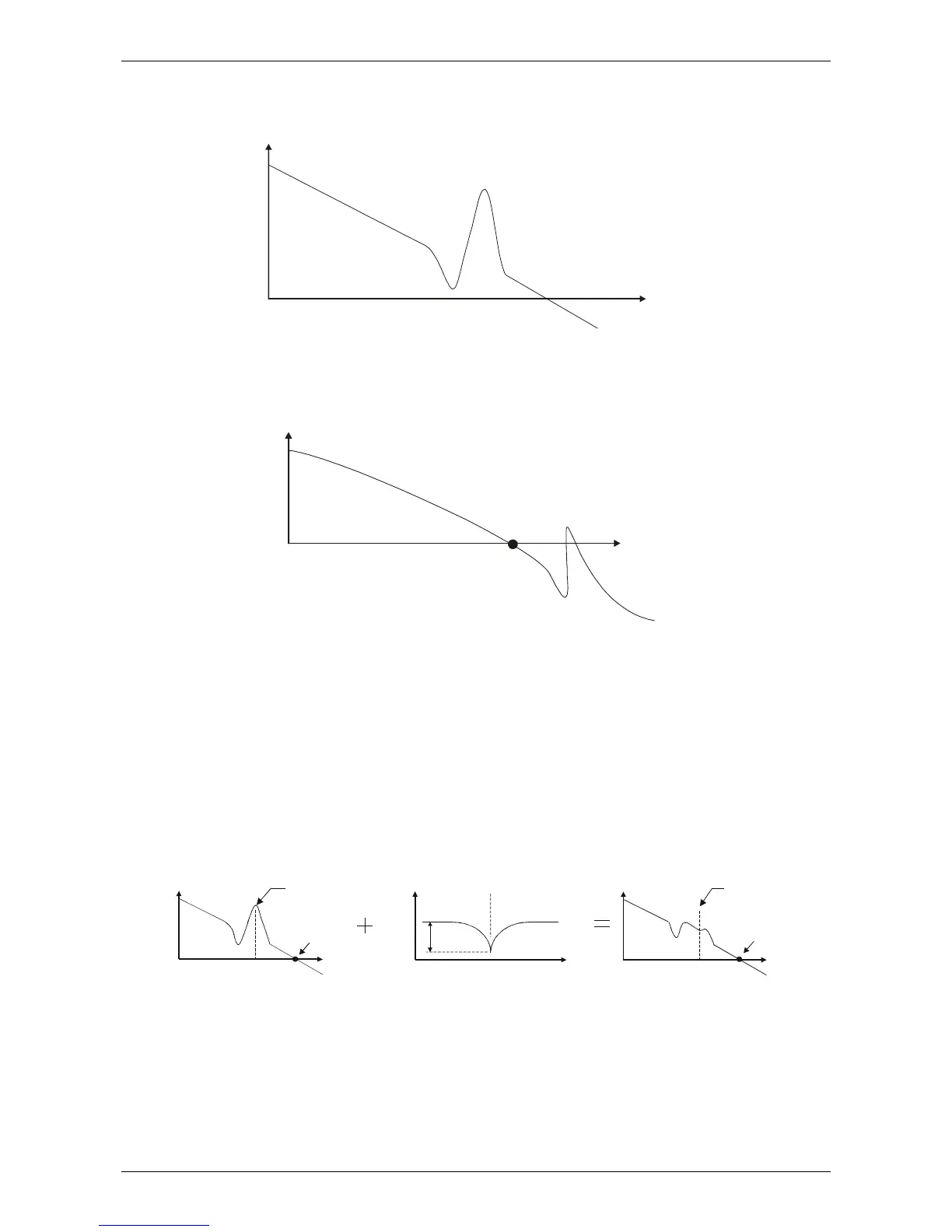
If users know the resonance frequency, notch filter (parameter P2-23 and P2-24) can directly
eliminate the resonance. The frequency setting range of notch filter is merely from 50 to 1000Hz.
The suppression strength is from 0 to 32dB. If the resonance frequency is not within the range, it is
suggested to use low-pass filter (parameter P2-25).
Here firstly illustrates the influence brought by notch filter (P2-23 and P2-24) and low-pass filter
(P2-25). The following diagrams are the system of open-loop gain with resonance.
Resonance suppression with notch filter
0db
Notch Filter
Attenuation
Rate P2-24
Resonance
Frequency
.
Resonance
Point
Gain
Frequency
.
Gain
Frequency
Gain
Frequency
Low-pass
Frequency
Low-pass
Frequency
Resonance
Frequency
P2-23
Resonance
conditions
is suppressed
Resonance
Frequency