EasyManuals Logo

Delta ASDA-A2 User Manual

Delta ASDA-A2
721 pages
To Next Page IconTo Next Page
To Previous Page IconTo Previous Page
Page #660 background imageLoading...
Page #660 background image
Chapter 12 Absolute System ASDA-A2
Revision February, 2017 12-11
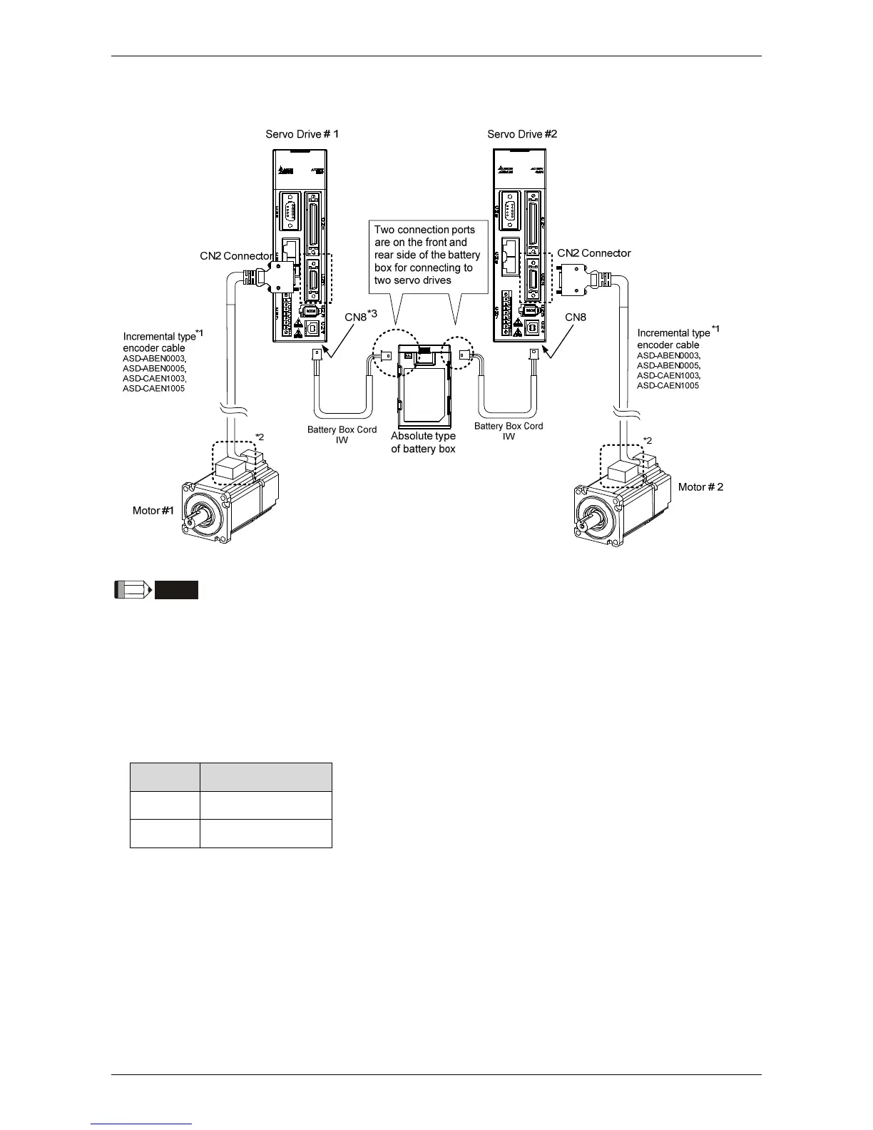
Dual Battery Box (Connect to CN8)
NOTE
This is the wiring diagram for connecting to a single battery box. The scale of the objects does not
match the dimensions as shown in the drawing above. For different models of AC servo drives and
motors, the connection cables may differ.
1* and 2* Please refer to section 12.1.3.
3* Definition of CN8 connector
Please conduct the wiring according to the following instructions. Wrong wiring might
cause battery explosion.
Pin No Terminal Symbol
1 BAT+
2 BAT-

Table of Contents

Other manuals for Delta ASDA-A2

Questions and Answers:

Question and Answer IconNeed help?

Do you have a question about the Delta ASDA-A2 and is the answer not in the manual?

Delta ASDA-A2 Specifications

General IconGeneral
Control ModePosition, Speed, Torque
ModelASDA-A2 Series
Operating Voltage200 ~ 230VAC / 380 ~ 480VAC
Power Supply200-230VAC ±10%, single-phase
Communication InterfaceRS-485, CANopen
FeedbackIncremental encoder, Absolute encoder
ProtectionOvercurrent, Overvoltage, Undervoltage, Overheating, Short Circuit
Operating Temperature0°C
Storage Temperature-20°C
Humidity20% to 90% RH (non-condensing)
Position Control Mode FeaturesElectronic Cam
WeightVaries depending on the model. Please refer to the specific model's datasheet.

Related product manuals