EasyManua.ls Logo

Delta ASDA-A2 User Manual

Delta ASDA-A2
721 pages
To Next Page IconTo Next Page
To Previous Page IconTo Previous Page
Page #462 background imageLoading...
Page #462 background image
ASDA-A2 Chapter 8 Parameters
Revision February, 2017 8-211
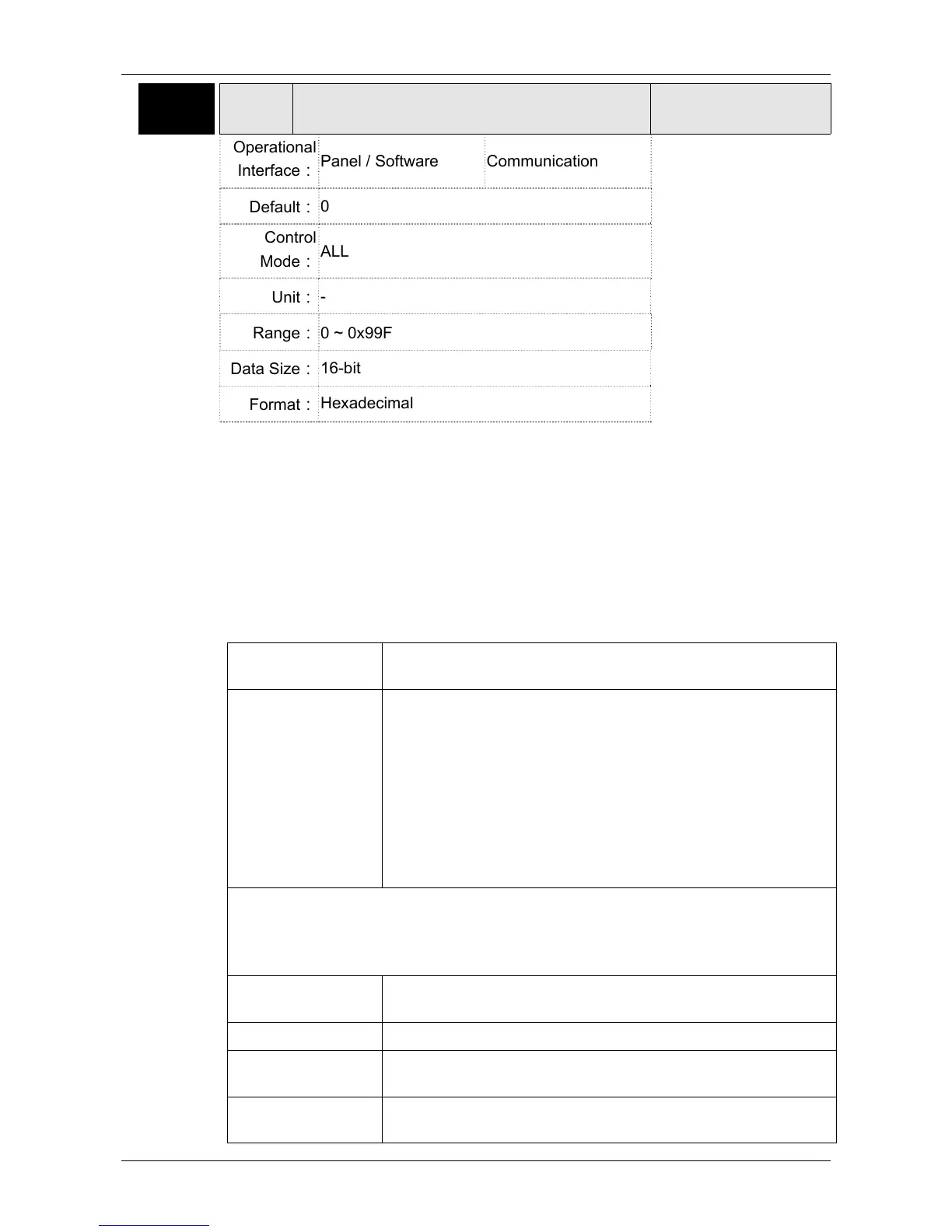
P5-97
CSDS
Motion Control Macro Command: Issue
Command / Executing Result
Address: 05C2H
05C3H
Operational
Interface
Panel / Software Communication
Related Section: -
Default
0
Control
Mode
ALL
Unit
-
Range
0 ~ 0x99F
Data Size
16-bit
Format
Hexadecimal
Settings
Write-in: It is used to issue the macro command (0CBAh)
Read: It is used to examine the execution result of macro command (If
success, the result will be sent back to 1CBAh).
If the command issues 0001, 1001h will be sent back when success;
and Fxxxh when failed (depending on the command description).
If issuing the command that is not supported, the failure code F001h
will be sent back.
The provided command code is as the followings.
The following macros are available from Version V1.027 (included):
Command code
0003h
Motion parameter protection: password setting, protection
activation
Macro parameters P5-93= Parameter write-protected level (0~1) (0 means no
protection)
P5-94= Protection level of data array (0~7) (-1 means no
protection)
P5-95= Set new password (1~16777215)
P5-96= Confirm new password (1~16777215)
Among them:
For success setting, the setting of P5-95 must equal to P5-96
and the password must be set within the allowable range.
This function can be executed before activating the function of parameter
protection.
If the protection function is activated, when repeat execute this function, the failure
code will be sent back.
Failure code F031h Protection function has been activated and cannot be set
repeat.
Failure code F032h Wrong password setting: P5-95 not equals to P5-96.
Failure code F033h Password setting exceeds the allowable range
(1~16777215).
Failure code F034h The protection level, P5-94 exceeds the allowable range (-
1~7).

Table of Contents

Other manuals for Delta ASDA-A2

Question and Answer IconNeed help?

Do you have a question about the Delta ASDA-A2 and is the answer not in the manual?

Delta ASDA-A2 Specifications

General IconGeneral
Control ModePosition, Speed, Torque
ModelASDA-A2 Series
Operating Voltage200 ~ 230VAC / 380 ~ 480VAC
Power Supply200-230VAC ±10%, single-phase
Communication InterfaceRS-485, CANopen
FeedbackIncremental encoder, Absolute encoder
ProtectionOvercurrent, Overvoltage, Undervoltage, Overheating, Short Circuit
Operating Temperature0°C
Storage Temperature-20°C
Humidity20% to 90% RH (non-condensing)
Position Control Mode FeaturesElectronic Cam
WeightVaries depending on the model. Please refer to the specific model's datasheet.

Summary

Preface

Safety Precautions

Highlights potential hazards and prohibited activities during operation, installation, and wiring.

Chapter 3 Wiring

3.4 I/O Signal (CN1) Connection

Details the terminal layout and signal descriptions for the CN1 connector.

Chapter 4 Panel Display and Operation

4.2 Parameter Setting Procedure

Outlines the steps for switching modes and operating within Monitor, Parameter, and Alarm modes.

4.4 General Function

Covers operations like fault record display, JOG mode, forced DO output, and digital input/output diagnosis.

Chapter 5 Trial Operation and Tuning

5.1 Inspection without Load

Provides checks before operation and after applying power, focusing on safety and wiring.

5.2 Applying Power to the Servo Drive

Instructions on correctly wiring the motor and applying power, including checks for 220V and 400V drives.

5.6 Tuning Procedure

Guides on estimating inertia ratio using JOG mode and tuning procedures like auto and semi-auto tuning.

Chapter 6 Control Mode of Operation

6.1 Selection of Operation Mode

Lists and describes single and dual control modes: Position, Speed, Torque, and CANopen.

6.2 Position Mode

Details the settings and related information for Position Mode, including PT and PR commands.

6.3 Speed Mode

Explains speed control modes (S, Sz) with analog and register inputs, including S-curve and gain adjustments.

6.4 Torque Mode

Details torque control modes (T, Tz) with analog input and register command sources.

Chapter 7 Motion Control

7.9 DI / DO Provided by PR Mode and Diagrams

Lists DI signals (CTRG, SHOM, STP, etc.) and DO signals (CMD_OK, MC_OK, TPOS, etc.) used in PR mode.

7.10 Parameter Settings

Details parameters for target speed, acceleration/deceleration time, pause time, and PR mode settings.

7.11 The Description of E-Cam Function

Explains E-Cam as a virtual cam, comparing it with machine cams and detailing features.

Chapter 8 Parameters

8.2 List of Parameters

Provides a comprehensive list of parameters, their functions, default values, and related sections.

8.3 Parameter Description

Detailed descriptions of P0-xx Monitor Parameters, including firmware version and alarm codes.

Chapter 9 Communications

9.1 RS-485 & RS-232 Communication Hardware Interface

Explains the hardware interface for RS-485 and RS-232 communication.

9.2 RS-485 / RS-232 Communication Parameters Setting

Details essential parameters like Address Setting, Transmission Speed, Protocol, and Mechanism.

9.3 MODBUS Communication Protocol

Describes MODBUS communication modes (ASCII, RTU) and character structure.

9.4 Write-in and Read-out Communication Parameters

Covers parameters that can be written or read via communication and provides notes on their usage.

Chapter 10 Troubleshooting

10.1 Alarm of Servo Drive

Lists common servo drive alarms, their descriptions, corresponding DO, and servo status.

10.2 Alarm of CANopen Communication

Details CANopen communication alarms, including SDO Rx Buffer overflow, PDO Rx Buffer overflow, and Index errors.

10.3 Alarm of Motion Control

Lists alarms related to motion control, such as CANopen data loading errors and PR parameter range issues.

10.4 Causes and Corrective Actions

Provides a table of common causes, checking methods, and corrective actions for various servo drive alarms.

10.5 Corrective Actions after the Alarm Occurs

Offers corrective actions for specific alarms like Over current, Over voltage, and Encoder errors.

Chapter 11 Specifications

Chapter 12 Absolute System

12.3 System Initialization Procedure and Operation

Details system initialization steps, including homing and parameter settings.

12.7 Alarms for Absolute System

Lists absolute system alarms, their descriptions, and corrective actions.

Appendix B Maintenance and Inspection

Inspection Before Operation

Pre-operation checks before power application and before running the servo drive.

Related product manuals