ASDA-A2 Chapter 8 Parameters
Revision February, 2017 8-279
Table 8.1 Function Description of Digital Input (DI)
Setting Value: 0x01
DI Name Function Description of Digital Input (DI)
Trigger
Method
Control
Mode
SON When this DI is On, servo is activated (Servo On) Level
triggered
ALL
Setting Value: 0x02
DI Name Function Description of Digital Input (DI)
Trigger
Method
Control
Mode
ARST After the alarm has been cleared, when the DI is ON the drive will
show that the alarm has been cleared.
Rising
edge
triggered
ALL
Setting Value: 0x03
DI Name Function Description of Digital Input (DI)
Trigger
Method
Control
Mode
GAINUP In speed and position mode, when the DI is ON (P2-27 should be
set to 1), the gain switched to the one multiplies the switching
rate.
Level
triggered
PT, PR, S
Setting Value: 0x04
DI Name Function Description of Digital Input (DI)
Trigger
Method
Control
Mode
CCLR Clear the pulse counter and the setting of parameter P2-50.
0: clear the position pulse deviation (It is suitable in PT mode).
When DI is ON, the accumulative pulse deviation of the drive will
be cleared to 0.
Rising
edge
triggered,
Level
triggered
PT, PR
Setting Value: 0x05
DI Name Function Description of Digital Input (DI)
Trigger
Method
Control
Mode
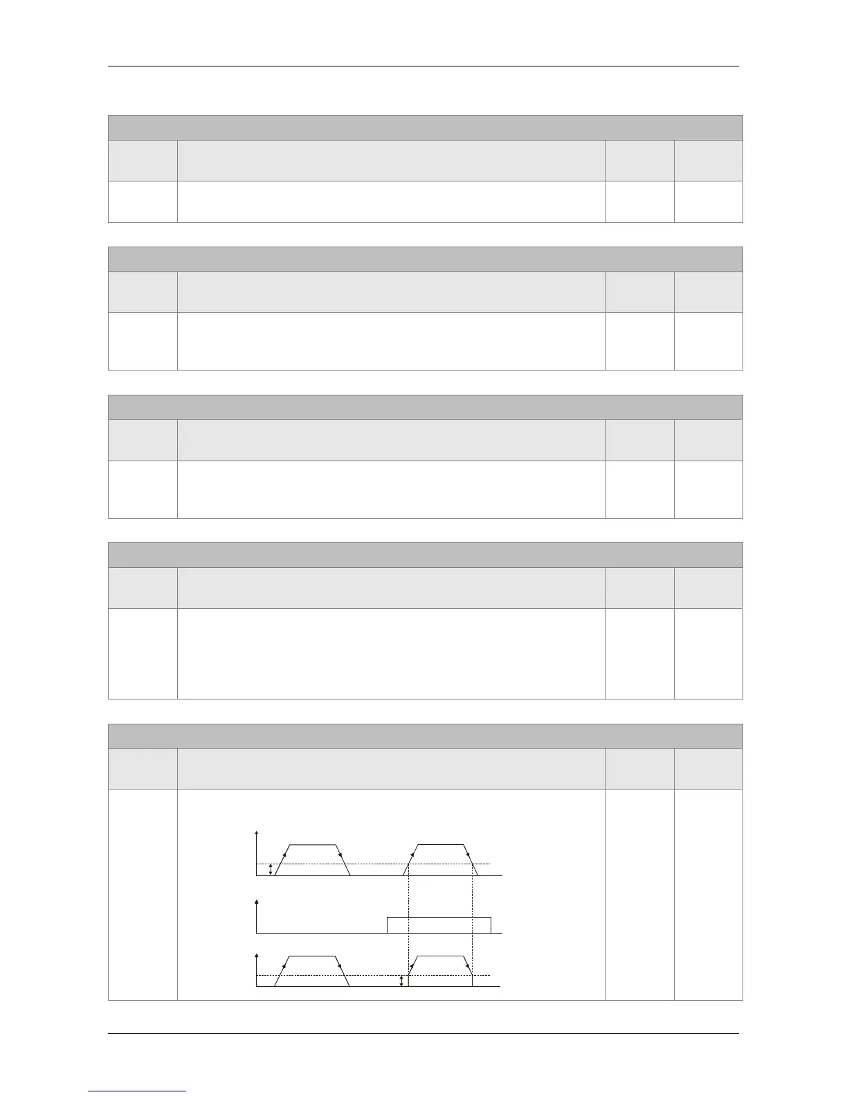
ZCLAMP When the speed is slower than the setting of zero speed (P1-38),
if the DI is ON, the motor stops running.
Level
triggered
S
Time
Setting value of
P1-38 (Zero speed)
OFF
ZCLAMP
input signal
Motor Speed
ON
Speed
Command
Setting value of
P1-38 (Zero speed)