Chapter 8 Parameters ASDA-A2
8-200 Revision February, 2017
Settings:
When synchronous capture axis is operating, the synchronous error
should be 0. This parameter shows this error value. The followings are
its concept:
Synchronous Error = Output value of synchronous axis-Setting
value of synchronous axis
= the accumulative amount of P5-77-(P5-78 x
Capturing number of times)
When capturing the data, the synchronous axis works normally. This
parameter updates once.
This parameter can be written into as well. It indicates the offset of
synchronous master. When the synchronous capture axis is regarded
as the master of flying shear, modify this parameter can deviate the
cutting position to the left/right.
NOTE
A2L does not support E-Cam function.
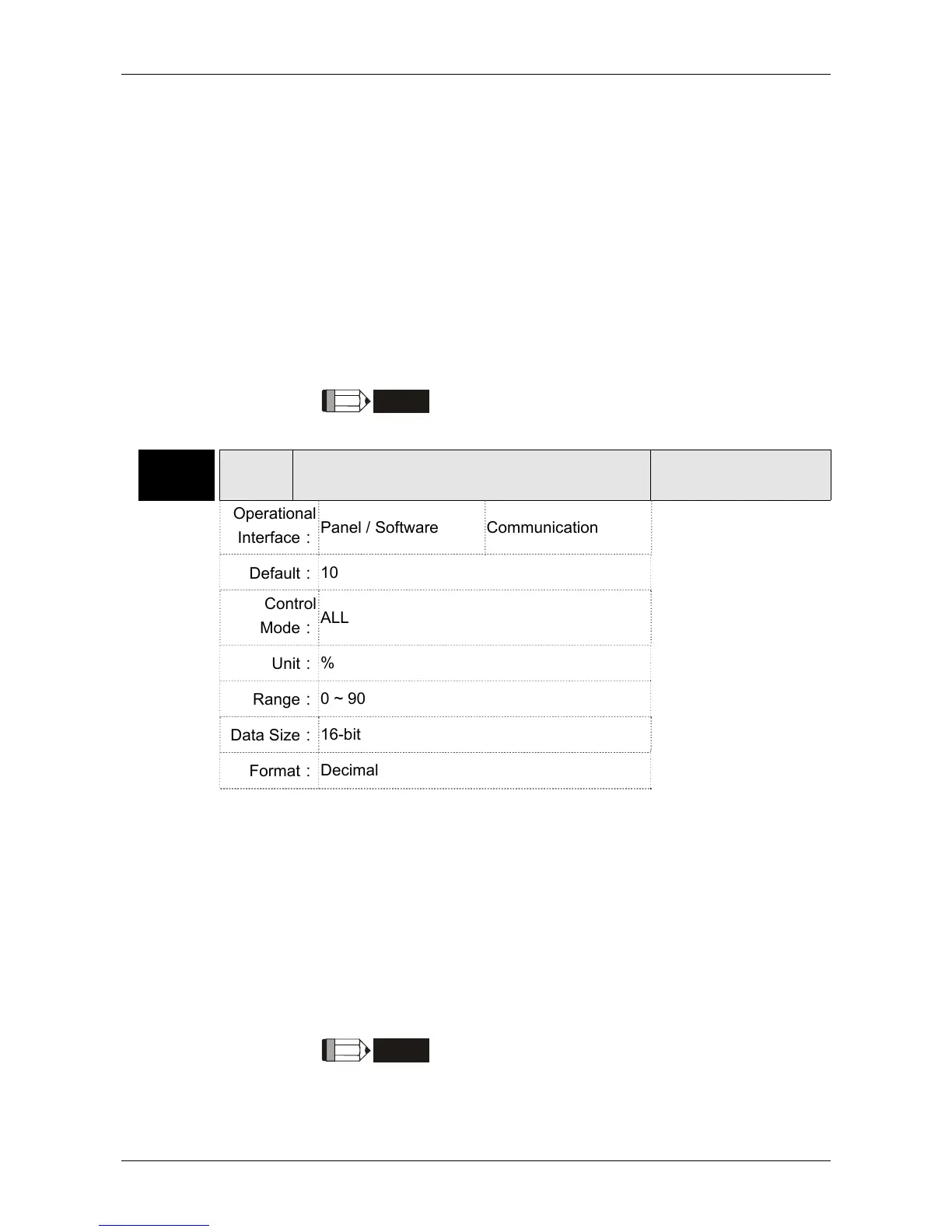
P5-80 CSDS
Max. Correction Rate of Synchronous Capture
Axis
Address: 05A0H
05A1H
Operational
Interface:
Panel / Software Communication
Related Section: -
Default:
10
Control
Mode:
ALL
Unit:
%
Range:
0 ~ 90
Data Size:
16-bit
Format:
Decimal
Settings:
This parameter limits the percentage (%) of synchronous adjustment.
Correctionrate
pulsenumberoutputbysynchronousaxis
/pulsenumberinputbysynchronousaxis
100 P5
80
% 100 5 80%
The bigger correction rate, the faster the synchronous error becomes
0. However, the speed changing will be more severe.
The smaller correction rate, the slower the synchronous error becomes
0. However, the speed changing will be smoother.
In the application of flying shear, after adjusting the synchronous error,
P5-79: the bigger parameter value will reduce the time the slave axis
goes to the desired position. However, the speed is not synchronized.
NOTE
A2L does not support E-Cam function.

 Loading...


