EasyManuals Logo

Delta ASDA-A2 User Manual

Delta ASDA-A2
721 pages
To Next Page IconTo Next Page
To Previous Page IconTo Previous Page
Page #186 background imageLoading...
Page #186 background image
ASDA-A2 Chapter 6 Control Mode of Operation
Revision February, 2017 6-31
6.3.5 Timing Diagram in Speed Mode
S4 (P1-11)
S3 (P1-10)
S2 (P1-09)
S1
SPD0
SPD1
SON
OFF
ON
OFF
ON
ON
OFF
ON
Internal speed
command
External analog
voltage or zero (0)
External I/O signal
NOTE
1) OFF means the contact point is open while ON means the contact point is
close.
2) When it is in Sz mode, the speed command S1 = 0; When it is in S mode,
the speed command S1 is the external analog voltage input.
3) When the servo drive is On, please select the command according to
SPD0~SPD1 status.
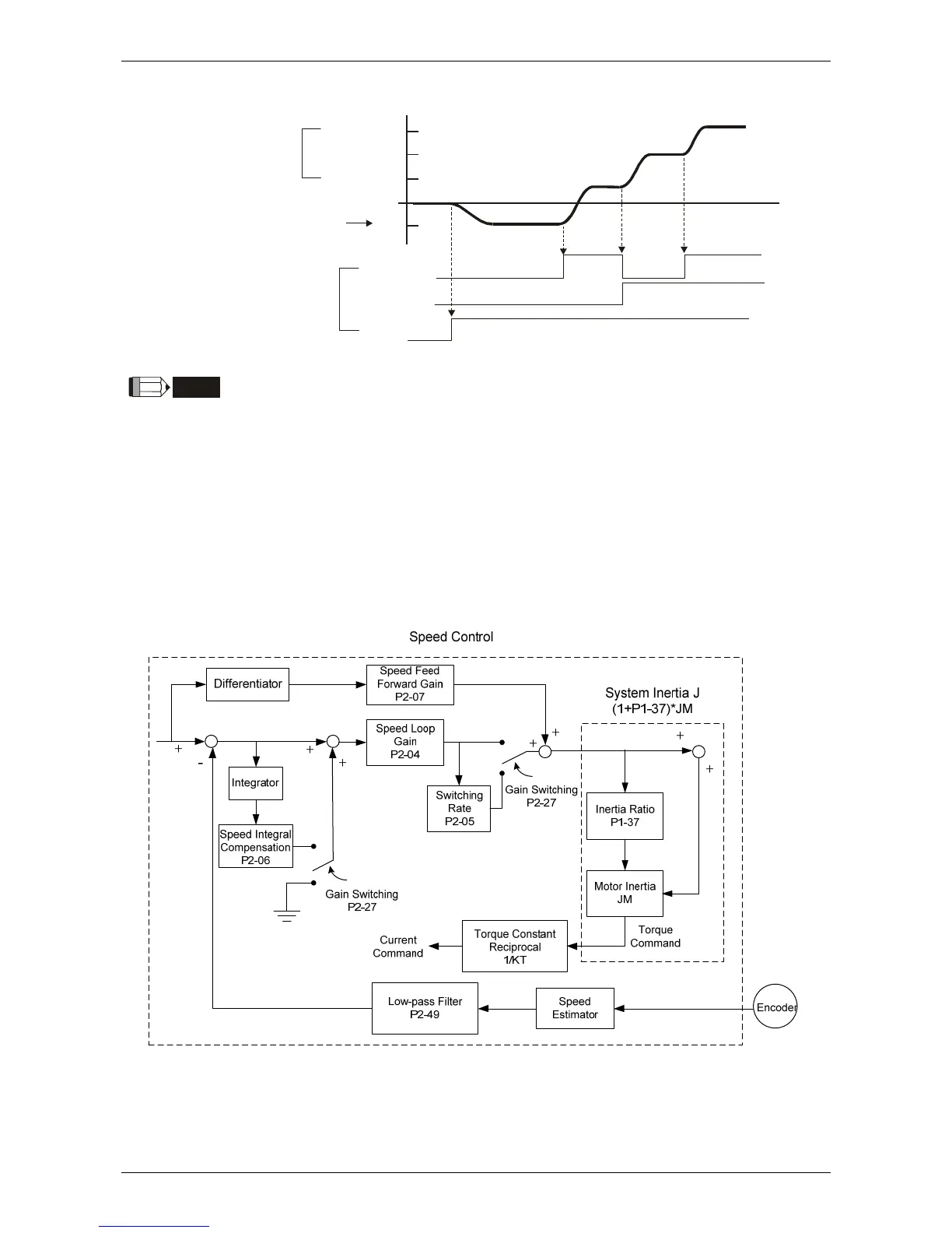
6.3.6 Gain Adjustment of Speed Loop
Here introduces the function of speed control unit. The following shows its structure.
Many kinds of gain in speed control unit are adjustable. Two ways, manual and auto, are provided
for selection.

Table of Contents

Other manuals for Delta ASDA-A2

Questions and Answers:

Question and Answer IconNeed help?

Do you have a question about the Delta ASDA-A2 and is the answer not in the manual?

Delta ASDA-A2 Specifications

General IconGeneral
Control ModePosition, Speed, Torque
ModelASDA-A2 Series
Operating Voltage200 ~ 230VAC / 380 ~ 480VAC
Power Supply200-230VAC ±10%, single-phase
Communication InterfaceRS-485, CANopen
FeedbackIncremental encoder, Absolute encoder
ProtectionOvercurrent, Overvoltage, Undervoltage, Overheating, Short Circuit
Operating Temperature0°C
Storage Temperature-20°C
Humidity20% to 90% RH (non-condensing)
Position Control Mode FeaturesElectronic Cam
WeightVaries depending on the model. Please refer to the specific model's datasheet.

Related product manuals