417-01-13 Exterior Lighting 417-01-13
DIAGNOSIS AND TESTING (CONTINUED)
CONDITIONS
DETAILS/RESULTS/ACTIONS
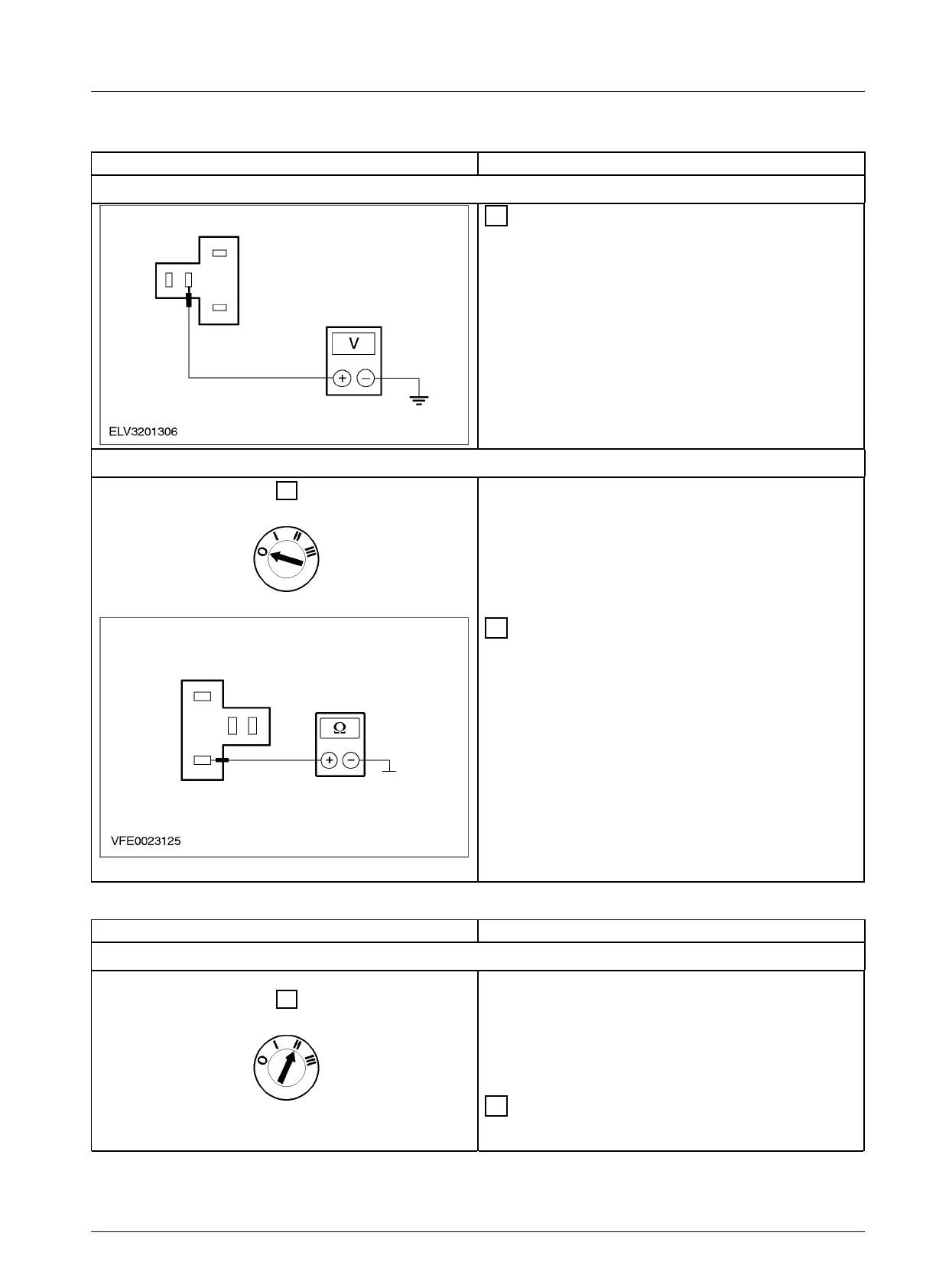
C3: CHECK THE POWER SUPPLY OF RELAY – HIGH BEAM
1 Measure the voltage between relay socket –
high beam, connector C5, pin 5, circuit 30-
LE13 (RD) and ground.
• Is battery voltage indicated?
Yes
GO TO C4
No
REPAIR the power supply of relay – high
beam, by using the wiring diagrams. TEST
the system for normal operation.
C4: CHECK THE GROUND CONNECTION OF RELAY – HIGH BEAM
1.
2 Measure the resistance between relay socket –
high beam, connector C5, pin 1, circuit 31-
LE12 (BK) and ground.
• Is the resistance less than 2 ohms?
Yes
INSTALL a new relay – high beam. TEST
the system for normal operation.
No
REPAIR the open circuit(s) between relay –
high beam and ground G6, by using the wir-
ing diagrams. TEST the system for normal
operation. If necessary INSTALL a new
CJB.
PINPOINT TEST D: ONE LOW BEAM HEADLAMP IS INOPERATIVE
CONDITIONS
DETAILS/RESULTS/ACTIONS
D1: DETERMINE THE FAULT CONDITION
1.
2 Turn the multifunction switch to the LOW
BEAM position.
E9418 EN 07/2001 2002 Bantam
BACK TO CHAPTER INDEX
FORD BANTAM
TO MODEL INDEX
PAGES FROM MANUAL