417-01-49 Exterior Lighting 417-01-49
DIAGNOSIS AND TESTING (CONTINUED)
CONDITIONS
DETAILS/RESULTS/ACTIONS
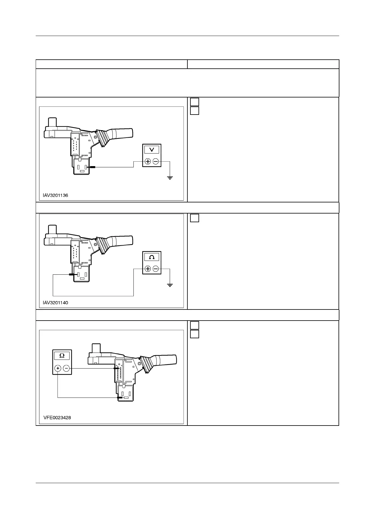
M5: CHECK THE POWER SUPPLY OF RELAY – TURN SIGNAL
1 Actuate the hazard warning switch.
2 Measure the voltage between relay socket –
turn signal, terminal 49 and ground.
• Is battery voltage indicated?
Yes
GO TO M6
No
CHECK the multifunction switch, according
to Component Testing attached to the wiring
diagrams. If necessary INSTALL a new one.
TEST the system for normal operation.
M6: CHECK THE GROUND CONNECTION OF RELAY – TURN SIGNAL
1 Measure the resistance between relay socket –
turn signal, terminal 31and ground.
• Is the resistance less than 2 ohms?
Yes
GO TO M7
No
CHECK the multifunction switch, according
to Component Testing attached to the wiring
diagrams. If necessary INSTALL a new one.
TEST the system for normal operation.
M7: CHECK THE MULTIFUNCTION SWITCH FOR PROPER FUNCTION
1 Actuate the hazard warning switch.
2 Measure the resistance between relay socket –
turn signal, terminal 49A, and multifunction
switch, connector C15a, pin 5, circuit 49-LG1
(BU), component side.
• Is the resistance less than 2 ohms?
Yes
INSTALL a new relay – turn signal. TEST
the system for normal operation.
No
INSTALL a new multifunction switch. TEST
the system for normal operation.
E9426 EN 07/2001 2002 Bantam
BACK TO CHAPTER INDEX
FORD BANTAM
TO MODEL INDEX
PAGES FROM MANUAL