MPC5604B/C Microcontroller Reference Manual, Rev. 8
Freescale Semiconductor 461
22.4.9.4 Protocol timing
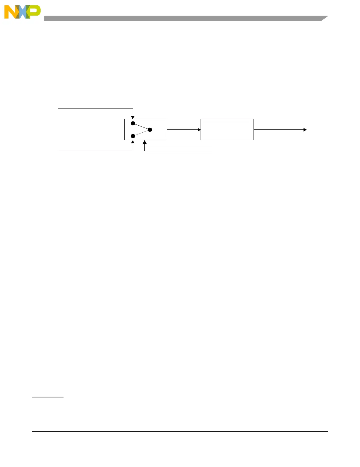
Figure 22-16 shows the structure of the clock generation circuitry that feeds the CAN Protocol Interface
(CPI) submodule. The clock source bit (CLK_SRC) in the CTRL Register defines whether the internal
clock is connected to the output of a crystal oscillator (Oscillator Clock) or to the Peripheral Clock
(generally from a FMPLL). In order to guarantee reliable operation, the clock source should be selected
while the module is in Disable Mode (bit MDIS set in the Module Configuration Register).
Figure 22-16. CAN engine clocking scheme
The crystal oscillator clock should be selected whenever a tight tolerance (up to 0.1%) is required in the
CAN bus timing. The crystal oscillator clock has better jitter performance than FMPLL generated clocks.
NOTE
This clock selection feature may not be available in all MCUs. A particular
MCU may not have a FMPLL, in which case it would have only the
oscillator clock, or it may use only the FMPLL clock feeding the FlexCAN
module. In these cases, the CLK_SRC bit in the CTRL Register has no
effect on the module operation.
The FlexCAN module supports a variety of means to setup bit timing parameters that are required by the
CAN protocol. The Control Register has various fields used to control bit timing parameters: PRESDIV,
PROPSEG, PSEG1, PSEG2 and RJW. See Section 22.3.4.2, “Control Register (CTRL).
The PRESDIV field controls a prescaler that generates the Serial Clock (Sclock), whose period defines the
‘time quantum’ used to compose the CAN waveform. A time quantum is the atomic unit of time handled
by the CAN engine.
A bit time is subdivided into three segments
1
(reference Figure 22-17 and Table 22-19):
• SYNC_SEG: This segment has a fixed length of one time quantum. Signal edges are expected to
happen within this section
• Time Segment 1: This segment includes the Propagation Segment and the Phase Segment 1 of the
CAN standard. It can be programmed by setting the PROPSEG and the PSEG1 fields of the CTRL
Register so that their sum (plus 2) is in the range of 4 to 16 time quanta
1. For further explanation of the underlying concepts please refer to ISO/DIS 11519–1, Section 10.3. Reference also the Bosch
CAN 2.0A/B protocol specification dated September 1991 for bit timing.
Peripheral Clock (FMPLL)
Oscillator Clock (Xtal)
CLK_SRC
Prescaler
(1 .. 256)
Sclock
CPI Clock
f
Tq
f
CANCLK
Prescaler ValueÞ
--------------------------------------------------------=