MPC5604B/C Microcontroller Reference Manual, Rev. 8
462 Freescale Semiconductor
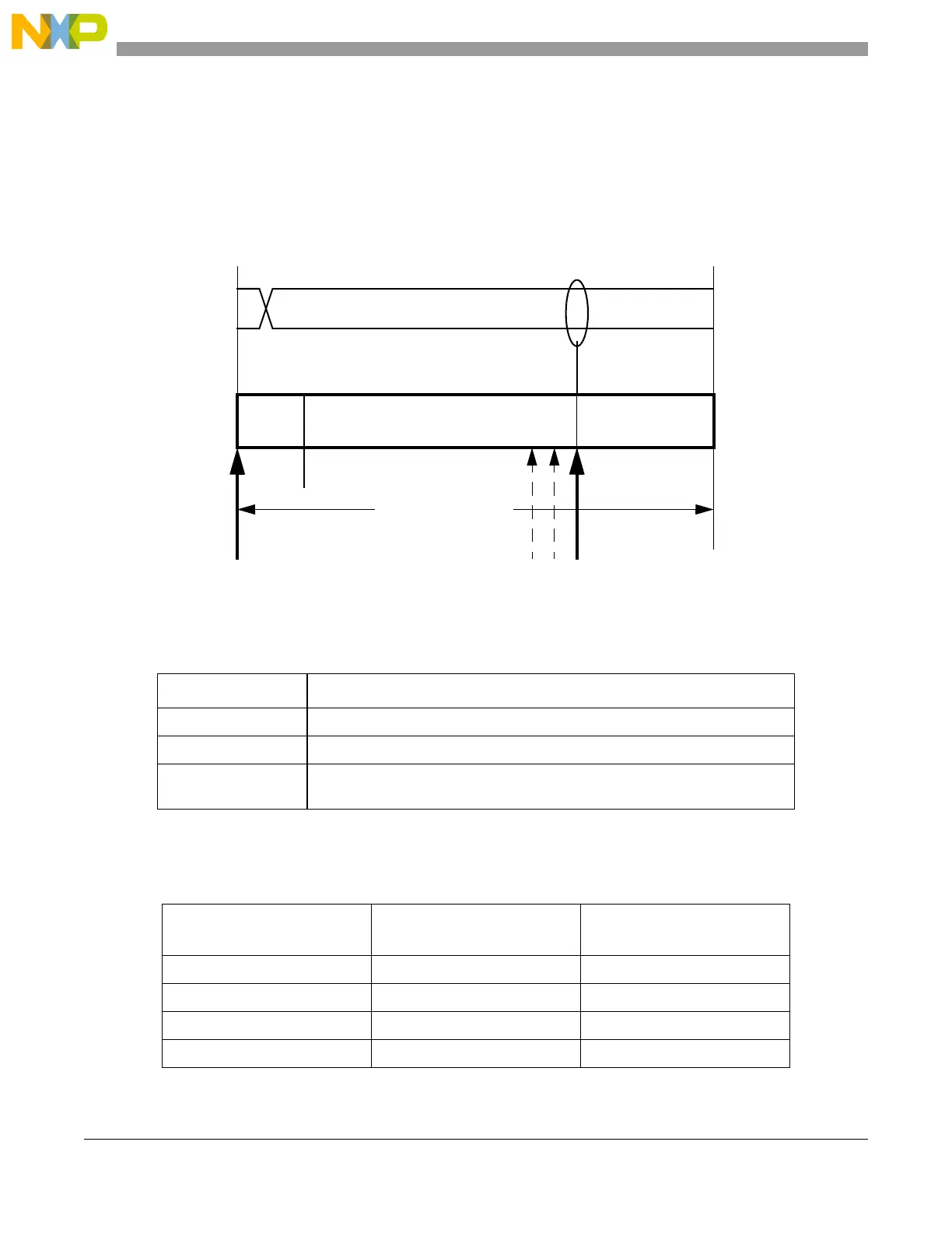
• Time Segment 2: This segment represents the Phase Segment 2 of the CAN standard. It can be
programmed by setting the PSEG2 field of the CTRL Register (plus 1) to be 2 to 8 time quanta long
Figure 22-17. Segments within the bit time
Table 22-20 is an example of the CAN compliant segment settings and the related parameter values. It
refers to the official CAN specification.
Table 22-19. Time segment syntax
Syntax Description
SYNC_SEG System expects transitions to occur on the bus during this period.
Transmit Point A node in transmit mode transfers a new value to the CAN bus at this point.
Sample Point A node samples the bus at this point. If the three samples per bit option is
selected, then this point marks the position of the third sample.
Table 22-20. CAN standard compliant bit time segment settings
Time segment 1 Time segment 2
Resynchronization jump
width
5 .. 10 2 1 .. 2
4 .. 11 3 1 .. 3
5 .. 12 4 1 .. 4
6 .. 13 5 1 .. 4
Bit Rate
f
Tq
number of Time QuantaÞÞ Þ
-----------------------------------------------------------------------------------------=Þ
SYNC_SEG
Time Segment 1 Time Segment 2
1 4 ... 16 2 ... 8
8 ... 25 Time Quanta
= 1 Bit Time
NRZ Signal
Sample Point
(single or triple sampling)
(PROP_SEG + PSEG1 + 2) (PSEG2 + 1)
Transmit Point
 Loading...