MPC5604B/C Microcontroller Reference Manual, Rev. 8
Freescale Semiconductor 563
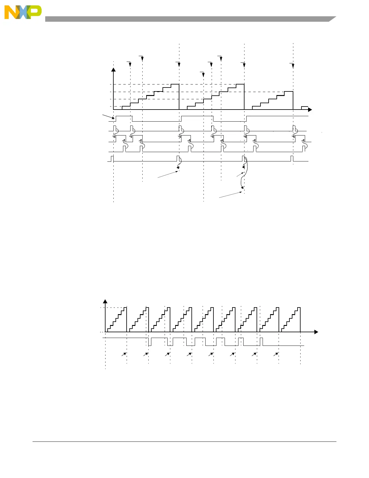
Figure 24-38. OPWFMB A1 and B1 registers update and flags
The FORCMA and FORCMB bits allow the software to force the output flip-flop to the level
corresponding to a match on comparators A or B respectively. Similarly to a B1 match FORCMB sets the
internal counter to 0x1. The FLAG bit is not set by the FORCMA or FORCMB bits being asserted.
Figure 24-39 describes the generation of 100% and 0% duty cycle signals. It is assumed EDPOL = 0 and
the resultant prescaler value is 1. Initially A1 = 0x8 and B1 = 0x8. In this case, B1 match has precedence
over A1 match, thus the output flip-flop is set to the complement of EDPOL bit. This cycle corresponds
to a 100% duty cycle signal. The same output signal can be generated for any A1 value greater or equal to
B1.
Figure 24-39. OPWFMB mode from 100% to 0% duty cycle
A 0% duty cycle signal is generated if A1 = 0x0 as shown in Figure 24-39 cycle 9. In this case B1 = 0x8
match from cycle 8 occurs at the same time as the A1 = 0x0 match from cycle 9. Please, refer to
EDPOL = 0
cycle n cycle n+1
cycle n+2
A1 value
1
B1 value
B2 value
0x8
0x2
0x6
0x8
0x1
internal counter
0x4
0x6
A2 value
1
0x2 0x4
0x6
0x2
0x4
0x6
0x8
0x6
Output pin
write to B2
write to A2
write to A2
Match A1
Match A1 Match B1
Match B1
Match B1
A1/B1 load signal
due to B1 match cycle n-1
FLAG set event
FLAG pin/register
Prescaler ratio = 4
FLAG clear
MODE[6] = 1
0x000008 0x000007 0x000006 0x000005 0x000004
0x000003
0x000002 0x000001 0x000000
0%
100%
EMIOSCNT
EDPOL = 0
A1 value
B1 value
Output pin
0x000008
Prescaler ratio = 1
cycle 1 cycle 2 cycle 3 cycle 4 cycle 5 cycle 6 cycle 7 cycle 8 cycle 9
0x000007 0x000006 0x000005 0x000004 0x000003
0x000002
0x000001 0x000000A2 value
0x000008
0x000001



 To Next Page