MPC5604B/C Microcontroller Reference Manual, Rev. 8
566 Freescale Semiconductor
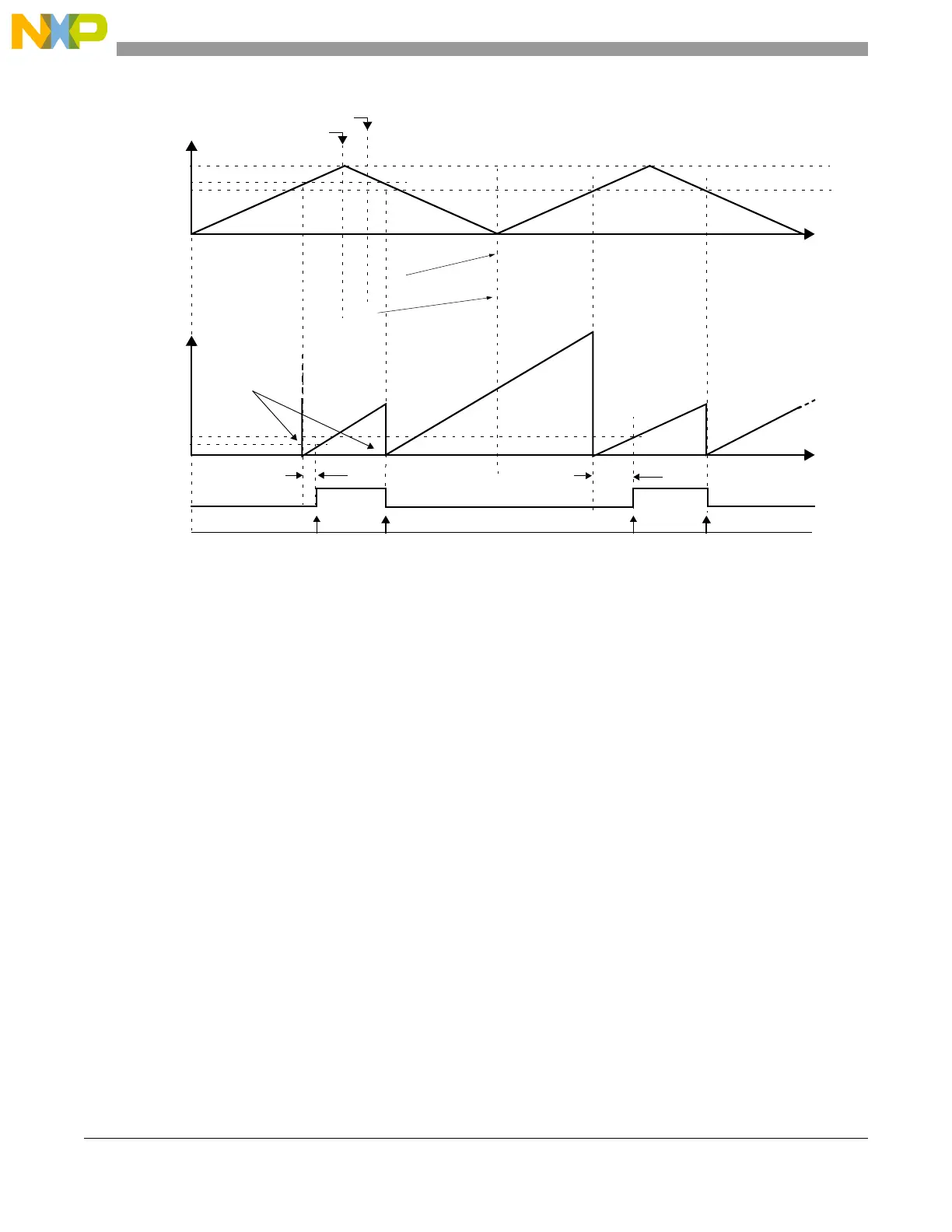
Figure 24-41. OPWMCB with lead dead time insertion
When operating with trailing edge dead time insertion, the first match between A1 and the selected time
base sets the output flip-flop to the value of the EDPOL bit and sets the internal counter to 0x1. In the
second match between register A1 and the selected time base, the internal counter is set to 0x1 and B1
matches are enabled. When the match between register B1 and the selected time base occurs the output
flip-flop is set to the complement of the EDPOL bit. This sequence repeats continuously.
EDPOL = 1
internal
time
base
internal counter is
set to 1 on A1 match
dead-time
A1 value
A2 value
B1 value
B2 value
write to B2
selected
counter bus
0x000002
0x000004
0x000002
0x000004
0x000015
0x000015
write to A2
0x000013
0x000013
0x000001
0x000002
0x000004
0x000015
0x000013
0x000020
dead-time
output flip-flop
FLAG pin/register
0x000001



 To Next Page